Toyota Yaris: Active Noise Control System / Front Right Microphone Circuit Component Internal Failure (B1AA696,B1AA71C)
DESCRIPTION
These DTCs are stored when a malfunction occurs in the active noise control microphone RH system.
| DTC No. | Detection Item | DTC Detection Condition | Trouble Area |
|---|---|---|---|
| B1AA696 | Front Right Microphone Circuit Component Internal Failure | Stereo component equalizer assembly detects malfunction in active noise control microphone RH for 4 seconds or more continuously when engine speed is 1200 rpm or more* |
|
| B1AA71C | Front Right Microphone Circuit Circuit Voltage Out of Range | Stereo component equalizer assembly detects active noise control microphone RH connection malfunction for 4 seconds or more continuously* |
|
HINT:
*: Malfunction monitoring is not performed under the following conditions, in order to prevent erroneous detection.
- After ignition switch is turned to ACC for 3 seconds or more.
- After the auxiliary battery voltage returns to normal for 3 seconds.
- Before 3 seconds have elapsed after auxiliary battery voltage has returned to normal.
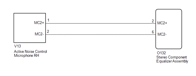
WIRING DIAGRAM
PROCEDURE
| 1. | CLEAR DTC |
(a) Clear the DTCs.
Body Electrical > Active Noise Control > Clear DTCs
|

| 2. | CHECK FOR DTC |
(a) Check for DTCs.
Body Electrical > Active Noise Control > Trouble Codes| Result | Proceed to |
|---|---|
| DTC B1AA696 and B1AA71C are not output | A |
| DTC B1AA696 and B1AA71C are output | B |
| A |
 | USE SIMULATION METHOD TO CHECK |
|

| 3. | CHECK HARNESS AND CONNECTOR (STEREO COMPONENT EQUALIZER ASSEMBLY - ACTIVE NOISE CONTROL MICROPHONE RH) |
(a) Disconnect the O132 stereo component equalizer assembly connector.
(b) Disconnect the V13 active noise control microphone RH connector.
(c) Measure the resistance according to the value(s) in the table below.
Standard Resistance:
| Tester Connection | Condition | Specified Condition |
|---|---|---|
| O132-2 (MC2+) - V13-1 (MC2+) | Always | Below 1 Ω |
| O132-6 (MC2-) - V13-2 (MC2-) | Always | Below 1 Ω |
| O132-2 (MC2+) - Body ground | Always | 10 kΩ or higher |
| O132-6 (MC2-) - Body ground | Always | 10 kΩ or higher |
| NG |
 | REPAIR OR REPLACE HARNESS OR CONNECTOR |
|

| 4. | REPLACE ACTIVE NOISE CONTROL MICROPHONE RH |
(a) Replace the active noise control microphone RH with a new or known good one.
Click here

|

| 5. | CLEAR DTC |
(a) Clear the DTCs.
Body Electrical > Active Noise Control > Clear DTCs
|

| 6. | CHECK FOR DTC |
(a) Check for DTCs.
Body Electrical > Active Noise Control > Trouble Codes| Result | Proceed to |
|---|---|
| DTC B1AA696 and B1AA71C are not output | A |
| DTC B1AA696 and B1AA71C are output | B |
| A |
 | END (ACTIVE NOISE CONTROL MICROPHONE RH IS DEFECTIVE) |
| B |
 | REPLACE STEREO COMPONENT EQUALIZER ASSEMBLY |
 Front Left Microphone Circuit Component Internal Failure (B1AA296,B1AA31C)
DESCRIPTION These DTCs are stored when a malfunction occurs in the active noise control microphone LH system. DTC No. Detection Item DTC Detection Condition Trouble Area B1AA296 Front Left Microphone Circuit Component Internal Failure Stereo component equalizer assembly detects malfunction in active noise control microphone LH for 4 seconds or more continuously when engine speed is 1200 rpm or more*
Harness or connector
Active noise control microphone LH
Stereo component equalizer assembly
B1AA31C Front Left Microphone Circuit Circuit Voltage Out of Range Stereo component equalizer assembly detects active noise control microphone LH connection malfunction for 4 seconds or more continuously*
Harness or connector
Active noise control microphone LH
Stereo component equalizer assembly
HINT: *: Malfunction monitoring is not performed under the following conditions, in order to prevent erroneous detection...
 Front Door Left Speaker Circuit Actuator Stuck (B1AAE71)
DESCRIPTION This DTC is output when a malfunction occurs in the left side front speaker system. DTC No. Detection Item DTC Detection Condition Trouble Area B1AAE71 Front Door Left Speaker Circuit Actuator Stuck When starting the system from IG OFF → ACC ON, the stereo component equalizer assembly detects a malfunction in the left side front speaker system*
Harness or connector
Front No...
Other information:
Toyota Yaris XP210 (2020-2026) Reapir and Service Manual: ECM/PCM Engine Off Timer Performance Signal Invalid (P261029)
DESCRIPTION The soak timer operates after the ignition switch is turned off. When a certain amount of time has elapsed after turning the ignition switch off, the soak timer activates the ECM to perform malfunction checks which can only be performed after the engine is stopped...
Toyota Yaris XP210 (2020-2026) Reapir and Service Manual: Diagnosis System
DIAGNOSIS SYSTEM DESCRIPTION (a) Lighting system data and Diagnostic Trouble Codes (DTCs) can be read from the Data Link Connector 3 (DLC3) of the vehicle. When the system seems to be malfunctioning, use the GTS to check for malfunctions and perform repairs...
Categories
- Manuals Home
- Toyota Yaris Owners Manual
- Toyota Yaris Service Manual
- Immobilizer System
- Engine & Hybrid System
- To Set Speed
- New on site
- Most important about car
Break-In Period
No special break-in is necessary, but a few precautions in the first 600 miles (1,000 km) may add to the performance, economy, and life of the vehicle.
Do not race the engine. Do not maintain one constant speed, either slow or fast, for a long period of time. Do not drive constantly at full-throttle or high engine rpm for extended periods of time. Avoid unnecessary hard stops. Avoid full-throttle starts.