Toyota Yaris: Front Suspension / Front Lower Suspension Arm
Components
COMPONENTS
ILLUSTRATION
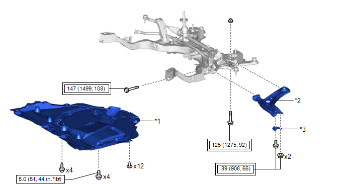
| *1 | NO.1 ENGINE UNDER COVER ASSEMBLY | *2 | FRONT LOWER NO. 1 SUSPENSION ARM SUB-ASSEMBLY |
| *3 | INNER NO. 1 ARM ATTACHMENT PLATE | - | - |
 | Tightening torque for "Major areas involving basic vehicle performance such as moving/turning/stopping" : N*m (kgf*cm, ft.*lbf) |
 | N*m (kgf*cm, ft.*lbf): Specified torque |
Removal
REMOVAL
CAUTION / NOTICE / HINT
The necessary procedures (adjustment, calibration, initialization, or registration) that must be performed after parts are removed, installed, or replaced during the front lower No. 1 suspension arm sub-assembly LH removal/installation are shown below.
Necessary Procedure After Parts Removed/Installed/Replaced| Replacement Part or Procedure | Necessary Procedure | Effect/Inoperative when not Performed | Link |
|---|---|---|---|
| Front wheel alignment adjustment | ECU Data Initialization | Active torque split AWD system |
|
| Calibration |
|
|


HINT:
- Use the same procedure for the RH side and LH side.
- The following procedure is for the LH side.
PROCEDURE
1. REMOVE FRONT WHEEL
Click here

2. REMOVE NO.1 ENGINE UNDER COVER ASSEMBLY
Click here

3. REMOVE FRONT LOWER NO. 1 SUSPENSION ARM SUB-ASSEMBLY
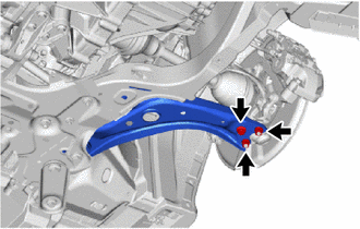
| (a) Remove the bolt, 2 nuts and separate the front lower No. 1 suspension arm sub-assembly from the front lower ball joint assembly. |
|
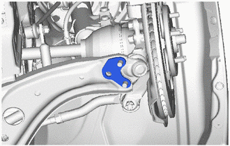
| (b) Remove inner No. 1 arm attachment plate from the front lower No. 1 suspension arm sub-assembly. |
|
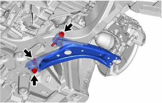
| (c) Remove the 2 bolts, nut and front lower No. 1 suspension arm sub-assembly from the front suspension crossmember sub-assembly. NOTICE: Do not turn the nut. Loosen the bolt with the nut secured. |
|
Installation
INSTALLATION
CAUTION / NOTICE / HINT
HINT:
- Use the same procedure for the RH side and LH side.
- The following procedure is for the LH side.
PROCEDURE
1. TEMPORARILY INSTALL FRONT LOWER NO. 1 SUSPENSION ARM SUB-ASSEMBLY
(a) Temporarily install the front lower No. 1 suspension arm sub-assembly to the front suspension crossmember sub-assembly with the 2 bolts and nut.
(b) Connect the front lower No. 1 suspension arm sub-assembly and inner No. 1 arm attachment plate to the front lower ball joint assembly with the bolt and 2 nuts.
Torque:
89 N·m {908 kgf·cm, 66 ft·lbf}
2. INSTALL FRONT WHEEL
Click here

3. STABILIZE SUSPENSION
(a) Press down on the vehicle several times to stabilize the suspension.
4. FULLY TIGHTEN FRONT LOWER NO. 1 SUSPENSION ARM SUB-ASSEMBLY
| (a) Tighten the bolt (A). Torque: 147 N·m {1499 kgf·cm, 108 ft·lbf} |
|
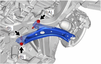
(b) Fully tighten the bolt (B).
Torque:
125 N·m {1275 kgf·cm, 92 ft·lbf}
NOTICE:
Tighten the bolt with the nut secured.
5. INSTALL NO.1 ENGINE UNDER COVER ASSEMBLY
Click here

6. INSPECT AND ADJUST FRONT WHEEL ALIGNMENT
Click here

 Installation
INSTALLATION CAUTION / NOTICE / HINT HINT:
Use the same procedure for the RH side and LH side.
The following procedure is for the LH side.
PROCEDURE 1...

Other information:
Toyota Yaris XP210 (2020-2026) Reapir and Service Manual: Removal
REMOVAL CAUTION / NOTICE / HINT The necessary procedures (adjustment, calibration, initialization, or registration) that must be performed after parts are removed and installed, or replaced during rear axle carrier sub-assembly removal/ installation are shown below...
Toyota Yaris XP210 (2020-2026) Reapir and Service Manual: Removal
REMOVAL CAUTION / NOTICE / HINT HINT: When the cable is disconnected/reconnected to the auxiliary battery terminal, systems temporarily stop operating. However, each system has a function that completes learning the first time the system is used. Learning completes when vehicle is driven Effect/Inoperative Function When Necessary Procedures are not Performed Necessary Procedures Link Lane tracing assist system Drive the vehicle straight ahead at 35 km/h (22 mph) or more for 5 second or more...
Categories
- Manuals Home
- Toyota Yaris Owners Manual
- Toyota Yaris Service Manual
- Key Battery Replacement
- How to connect USB port/Auxiliary jack
- Battery Monitor Module General Electrical Failure (P058A01)
- New on site
- Most important about car
Refueling
Before refueling, close all the doors, windows, and the liftgate/trunk lid, and switch the ignition OFF.
To open the fuel-filler lid, pull the remote fuel-filler lid release.
