Toyota Yaris: Smart Key System (for Start Function) / Antenna Coil Circuit Voltage Out of Range (B27841C)
DESCRIPTION
When an open or short circuit is detected in the transponder key amplifier coil built into the engine switch, the certification ECU (smart key ECU assembly) stores this DTC. This DTC is also stored as a history DTC.
| DTC No. | Detection Item | DTC Detection Condition | Trouble Area | Note |
|---|---|---|---|---|
| B27841C | Antenna Coil Circuit Voltage Out of Range | The transponder key amplifier coil built into the engine switch is open (see below) or shorted (determined by communication with certification ECU (smart key ECU assembly)). (1 trip detection logic*) |
|
|
- *: Only output while a malfunction is present.
| Vehicle Condition when Malfunction Detected | Fail-safe Operation when Malfunction Detected |
|---|---|
| Engine cannot be started when transmitter battery is depleted by holding electrical key transmitter sub-assembly near engine switch and pressing and holding engine switch. | - |
| DTC No. | Data List and Active Test |
|---|---|
| B27841C | - |
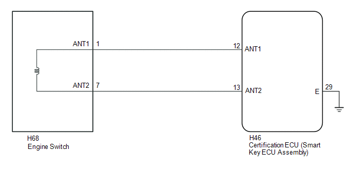
WIRING DIAGRAM
CAUTION / NOTICE / HINT
NOTICE:
- When using the GTS with the ignition switch off, connect the GTS to the DLC3 and turn a courtesy light switch on and off at intervals of 1.5 seconds or less until communication between the GTS and the vehicle begins. Then select the vehicle type under manual mode and enter the following menus: Body Electrical / Smart Key. While using the GTS, periodically turn a courtesy light switch on and off at intervals of 1.5 seconds or less to maintain communication between the GTS and the vehicle.
-
The smart key system (for Start Function) uses the LIN communication system and CAN communication system. Inspect the communication function by following How to Proceed with Troubleshooting. Troubleshoot the smart key system (for Start Function) after confirming that the communication systems are functioning properly.
Click here

-
Before replacing the certification ECU (smart key ECU assembly), refer to Registration.
Click here

- After performing repairs, confirm that no DTCs are output by performing "DTC Output Confirmation Operation".
PROCEDURE
| 1. | CHECK CONNECTION OF CONNECTOR |
(a) Check that the connectors are properly connected to the engine switch and certification ECU (smart key ECU assembly).
OK:
Connectors are properly connected.
| NG |
 | CONNECT CONNECTORS PROPERLY |
|

| 2. | CHECK HARNESS AND CONNECTOR (CERTIFICATION ECU (SMART KEY ECU ASSEMBLY) - ENGINE SWITCH AND BODY GROUND) |
(a) Disconnect the H46 certification ECU (smart key ECU assembly) connector.
(b) Disconnect the H68 engine switch connector.
(c) Measure the resistance according to the value(s) in the table below.
Standard Resistance:
| Tester Connection | Condition | Specified Condition |
|---|---|---|
| H46-12 (ANT1) - H68-1 (ANT1) | Always | Below 1 Ω |
| H46-12 (ANT1) or H68-1 (ANT1) - Body ground | Always | 10 kΩ or higher |
| H46-13 (ANT2) - H68-7 (ANT2) | Always | Below 1 Ω |
| H46-13 (ANT2) or H68-7 (ANT2) - Body ground | Always | 10 kΩ or higher |
| NG |
 | REPAIR OR REPLACE HARNESS OR CONNECTOR |
|

| 3. | CHECK CERTIFICATION ECU (SMART KEY ECU ASSEMBLY) |
(a) Connect the H46 certification ECU (smart key ECU assembly) connector.
(b) Using an oscilloscope, check the waveform.
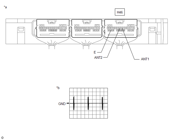
| *a | Component with harness connected (Certification ECU (Smart Key ECU Assembly)) | *b | Waveform 1 |
OK:
| Tester Connection | Condition | Tool Setting | Specified Condition |
|---|---|---|---|
| H46-12 (ANT1) - H46-29 (E) | Ignition switch off, electrical key transmitter sub-assembly not in cabin, within 30 seconds of engine switch pressed | 20 V/DIV., 200 ms./DIV. | Pulse generation (See waveform 1) |
| H46-13 (ANT2) - H46-29 (E) | Ignition switch off, electrical key transmitter sub-assembly not in cabin, within 30 seconds of engine switch pressed | 20 V/DIV., 200 ms./DIV. | Pulse generation (See waveform 2) |
| OK |
 | REPLACE ENGINE SWITCH |
| NG |
 | REPLACE CERTIFICATION ECU (SMART KEY ECU ASSEMBLY) |
 Power Source Control System Circuit Short to Battery or Open (B278215)
DESCRIPTION The certification ECU (smart key ECU assembly) has a power source mode switching function. This DTC is stored when the IGE input (the steering lock motor activation permission signal) sent directly from the certification ECU (smart key ECU assembly) to the steering lock ECU (steering lock actuator or upper bracket assembly) is determined to be abnormal...
 ID-BOX Component Internal Failure (B278D96)
DESCRIPTION When the certification ECU (smart key ECU assembly) detects an input signal indicating that the vehicle is equipped with an ID code box even though the ID code box is not registered, the certification ECU (smart key ECU assembly) stores this DTC...
Other information:
Toyota Yaris XP210 (2020-2025) Reapir and Service Manual: On-vehicle Inspection
ON-VEHICLE INSPECTION PROCEDURE 1. INSPECT NO. 1 TURBO PRESSURE SENSOR (a) Check the terminal voltage. (1) Disconnect the No. 1 turbo pressure sensor connector. (2) Turn the ignition switch to ON. (3) Measure the voltage according to the value(s) in the table below...
Toyota Yaris XP210 (2020-2025) Reapir and Service Manual: Internal Control Module Throttle Position Performance Internal Electronic Failure (P060E49)
MONITOR DESCRIPTION The ECM monitors the signals received from the No. 1 throttle position sensor. As the ECM monitors the VTA1 signal of the No. 1 throttle position sensor, if these signals do not correlate, a DTC will be stored. DTC No. Detection Item DTC Detection Condition Trouble Area MIL Note P060E49 Internal Control Module Throttle Position Performance Internal Electronic Failure Either of the following conditions is met (1 trip detection logic): ECM main CPU malfunction...
Categories
- Manuals Home
- Toyota Yaris Owners Manual
- Toyota Yaris Service Manual
- Maintenance
- Immobilizer System
- How to connect USB port/Auxiliary jack
- New on site
- Most important about car
Key Suspend Function
If a key is left in the vehicle, the functions of the key left in the vehicle are temporarily suspended to prevent theft of the vehicle.
To restore the functions, press the unlock button on the functions-suspended key in the vehicle.