Toyota Yaris: Fuel System / System Diagram
Toyota Yaris XP210 (2020-2026) Reapir and Service Manual / Engine & Hybrid System / G16e-gts (fuel) / Fuel System / System Diagram
SYSTEM DIAGRAM
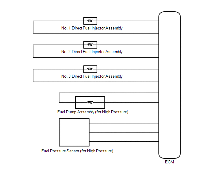
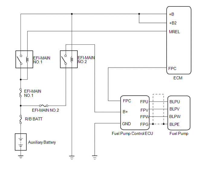
HIGH PRESSURE SIDE FUEL SYSTEM WIRING DIAGRAM
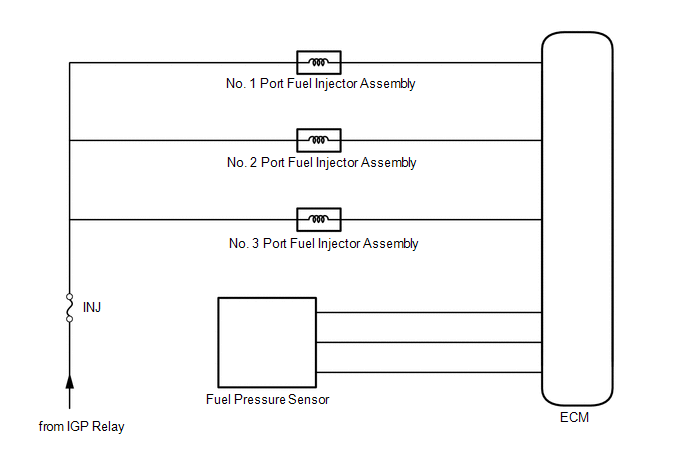
LOW PRESSURE SIDE FUEL SYSTEM WIRING DIAGRAM
 Parts Location
PARTS LOCATION ILLUSTRATION
*1 FUEL PUMP *2 FUEL SENDER GAUGE ASSEMBLY *3 NO. 2 FUEL SENDER GAUGE ASSEMBLY *4 FUEL PUMP CONTROL ECU *5 FUEL TANK ASSEMBLY *6 FUEL TANK VENT TUBE WITH SENDER GAUGE ASSEMBLY *7 FUEL SUCTION TUBE WITH PUMP AND GAUGE ASSEMBLY *8 FUEL MAIN VALVE ASSEMBLY *9 NO...
 On-vehicle Inspection
ON-VEHICLE INSPECTION PROCEDURE 1. CHECK FUEL PUMP OPERATION AND INSPECT FOR FUEL LEAK (a) Check fuel pump operation. (1) Connect the GTS to the DLC3. (2) Turn the ignition switch to ON...
Other information:
Toyota Yaris XP210 (2020-2026) Reapir and Service Manual: Removal
REMOVAL PROCEDURE 1. REMOVE BENCH TYPE REAR SEAT CUSHION ASSEMBLY Click here 2. REMOVE REAR SEAT CUSHION LOCK HOOK Click here 3. REMOVE REAR SEAT INNER BELT ASSEMBLY LH (a) Disconnect the connector. (b) Disengage the connector clamp...
Toyota Yaris XP210 (2020-2026) Owner's Manual: Windows
The windows can be opened/closed by operating the power window switches. When driving with only one of the rear windows open, your ears might experience a resonating sound. However, this does not indicate a problem. The sound can be reduced by slightly opening a front window or by changing the size of the rear window opening...
Categories
- Manuals Home
- Toyota Yaris Owners Manual
- Toyota Yaris Service Manual
- Battery Monitor Module General Electrical Failure (P058A01)
- Brake System Control Module "A" System Voltage System Voltage Low (C137BA2)
- Opening and Closing the Liftgate/Trunk Lid
- New on site
- Most important about car
Keys

To use the auxiliary key, press the knob and pull out the auxiliary key from the smart key.

Copyright © 2026 www.toyaris4.com