Toyota Yaris: Heating / Air Conditioning / Room Temperature Sensor
Components
COMPONENTS
ILLUSTRATION
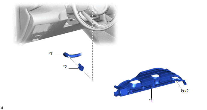
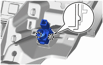
| *1 | NO. 1 INSTRUMENT PANEL UNDER COVER SUB-ASSEMBLY | *2 | COOLER THERMISTOR (ROOM TEMPERATURE SENSOR) |
| *3 | ASPIRATOR | - | - |
Removal
REMOVAL
PROCEDURE
1. REMOVE NO. 1 INSTRUMENT PANEL UNDER COVER SUB-ASSEMBLY
Click here

2. REMOVE COOLER THERMISTOR (ROOM TEMPERATURE SENSOR)
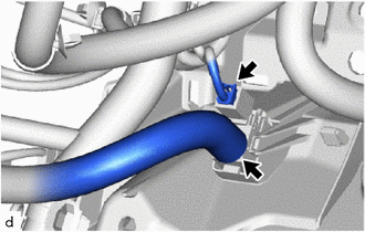
| (a) Disconnect the connector and aspirator. |
|
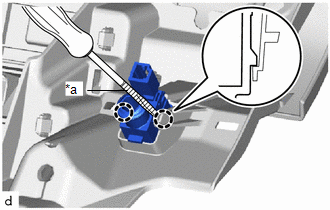
| (b) Using a screwdriver with its tip wrapped in protective tape, disengage the claws to remove the cooler thermistor (room temperature sensor). |
|
Inspection
INSPECTION
PROCEDURE
1. INSPECT COOLER THERMISTOR (ROOM TEMPERATURE SENSOR)
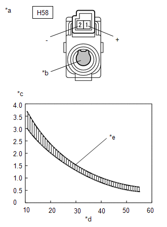
(a) Check the resistance.
| (1) Measure the resistance according to the value(s) in the table below. Standard Resistance:
NOTICE:
HINT: As the temperature increases, the resistance decreases (see the graph). If the result is not as specified, replace the cooler thermistor (room temperature sensor). |
|
Installation
INSTALLATION
PROCEDURE
1. INSTALL COOLER THERMISTOR (ROOM TEMPERATURE SENSOR)
| (a) Engage the claws to install the cooler thermistor (room temperature sensor). |
|
(b) Connect the connector and aspirator.
2. INSTALL NO. 1 INSTRUMENT PANEL UNDER COVER SUB-ASSEMBLY
Click here

 Refrigerant Line
ComponentsCOMPONENTS ILLUSTRATION
*1 PIPING CLAMP *2 SUCTION HOSE SUB-ASSEMBLY *3 O-RING *4 AIR CONDITIONER TUBE AND ACCESSORY ASSEMBLY *5 NO...
 Solar Sensor
..
Other information:
Toyota Yaris XP210 (2020-2026) Reapir and Service Manual: VSC OFF Switch Circuit
DESCRIPTION Operating the VSC OFF switch (combination switch assembly) makes it possible for TRC and/or VSC operation to be prohibited. Pressing the VSC OFF switch (combination switch assembly) changes to TRC OFF mode, and turns off TRC operation. In addition, a TRC cancel message is displayed on the multi-information display in the combination meter assembly...
Toyota Yaris XP210 (2020-2026) Reapir and Service Manual: How To Proceed With Troubleshooting
CAUTION / NOTICE / HINT HINT: Use the following procedure to troubleshoot the headup display system. *: Use the GTS. PROCEDURE 1. VEHICLE BROUGHT TO WORKSHOP NEXT 2. CUSTOMER PROBLEM ANALYSIS HINT: In troubleshooting, confirm that the problem symptoms have been accurately identified...
Categories
- Manuals Home
- Toyota Yaris Owners Manual
- Toyota Yaris Service Manual
- G16e-gts (engine Mechanical)
- How to use USB mode
- How to connect USB port/Auxiliary jack
- New on site
- Most important about car
Supplemental Restraint System (SRS) Precautions
The front and side supplemental restraint systems (SRS) include different types of air bags. Please verify the different types of air bags which are equipped on your vehicle by locating the “SRS AIRBAG” location indicators. These indicators are visible in the area where the air bags are installed.
The air bags are installed in the following locations:
The steering wheel hub (driver air bag) The front passenger dashboard (front passenger air bag) The outboard sides of the front seatbacks (side air bags) The front and rear window pillars, and the roof edge along both sides (curtain air bags)