Toyota Yaris: Air Conditioning System / Refrigerant Pressure Sensor Circuit Short to Battery or Open (P053015)
DESCRIPTION
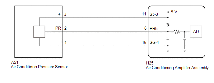
The air conditioner pressure sensor, which is installed to the high pressure side pipe to detect refrigerant pressure, sends a refrigerant pressure signal to the air conditioning amplifier assembly. The air conditioning amplifier assembly converts this signal to a pressure value according to the sensor characteristics and uses it to control the compressor.
| DTC No. | Detection Item | DTC Detection Condition | Trouble Area | Memory |
|---|---|---|---|---|
| P053015 | Refrigerant Pressure Sensor Circuit Short to Battery or Open | Diagnosis Condition:
Malfunction Status:
Detection Time:
|
| Memorized |
| Vehicle Condition | |||
|---|---|---|---|
| Pattern 1 | Pattern 2 | ||
| Diagnosis Condition | Ignition switch ON | ○ | ○ |
| Malfunction | Open in air conditioner pressure sensor circuit | ○ | - |
| Short in air conditioner pressure sensor circuit | - | ○ | |
| Detection Time | Continuously for 4 seconds or more | Continuously for 4 seconds or more | |
| Trip Count | 1 trip | 1 trip | |
HINT:
If the conditions of either of these patterns are detected, a DTC will be stored
WIRING DIAGRAM
PROCEDURE
| 1. | CHECK REGULATOR PRESSURE SENSOR |
(a) Install a manifold gauge set.
(b) Read the Data List according to the display on the GTS.
Body Electrical > Air Conditioner > Data List| Tester Display | Measurement Item | Range | Normal Condition | Diagnostic Note |
|---|---|---|---|---|
| Regulator Pressure Sensor | Air conditioner pressure sensor | Min.: -32.768 MPaG Max.: 32.767 MPaG | Actual refrigerant pressure displayed |
|
| Tester Display |
|---|
| Regulator Pressure Sensor |
(c) Compare the values displayed in the Data List and on the manifold gauge set.
| Result | Proceed to |
|---|---|
| The values displayed in the Data List and on the manifold gauge set does not match | A |
| The values displayed in the Data List and on the manifold gauge set match | B |
| B |
 | INSPECT REFRIGERANT PRESSURE WITH MANIFOLD GAUGE SET |
|

| 2. | CHECK HARNESS AND CONNECTOR (AIR CONDITIONER PRESSURE SENSOR - BODY GROUND) |
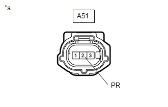
(a) Disconnect the A51 air conditioner pressure sensor connector.
(b) Measure the resistance according to the value(s) in the table below.
Standard Resistance:
| Tester Connection | Switch Condition | Specified Condition |
|---|---|---|
| A51-1 (-) - Body ground | Always | Below 1 Ω |
| NG |
 | GO TO STEP 8 |
|

| 3. | CHECK TERMINAL VOLTAGE |
| (a) Measure the voltage according to the value(s) in the table below. Standard Voltage:
|
|
| Result | Proceed to |
|---|---|
| Higher than 5.25 V | A |
| 3.0 to 5.25 V | B |
| Less than 3.0V | C |
| B |
 | GO TO STEP 5 |
| C |
 | GO TO STEP 7 |
|

| 4. | CHECK HARNESS AND CONNECTOR (AIR CONDITIONER PRESSURE SENSOR - AIR CONDITIONING AMPLIFIER ASSEMBLY) |
(a) Disconnect the H25 air conditioning amplifier assembly connector.
(b) Measure the resistance according to the value(s) in the table below.
Standard Resistance:
| Tester Connection | Condition | Specified Condition |
|---|---|---|
| A51-2 (PR) or H25-6 (PRE) - Other terminals and body ground | Always | 10 kΩ or higher |
| OK |
 | REPLACE AIR CONDITIONING AMPLIFIER ASSEMBLY |
| NG |
 | REPAIR OR REPLACE HARNESS OR CONNECTOR |
| 5. | CHECK INTERNAL CIRCUIT RESISTANCE (AIR CONDITIONING AMPLIFIER ASSEMBLY) |
(a) Measure the resistance according to the value(s) in the table below.
Standard Resistance:
| Tester Connection | Condition | Specified Condition |
|---|---|---|
| A51-3 (+) - A51-2 (PR) | Ignition switch off | 180 to 220 kΩ |
HINT:
After turning the ignition switch off, wait at least 30 seconds before performing the measurement.
| OK |
 | REPLACE AIR CONDITIONER PRESSURE SENSOR |
|

| 6. | CHECK HARNESS AND CONNECTOR (AIR CONDITIONER PRESSURE SENSOR - AIR CONDITIONING AMPLIFIER ASSEMBLY) |
(a) Disconnect the H25 air conditioning amplifier assembly connector.
(b) Measure the resistance according to the value(s) in the table below.
Standard Resistance:
| Tester Connection | Condition | Specified Condition |
|---|---|---|
| A51-2 (PR) or H25-6 (PRE) - A51-3 (+) or H25-11 (S5-3) | Always | 10 kΩ or higher |
| OK |
 | REPLACE AIR CONDITIONING AMPLIFIER ASSEMBLY |
| NG |
 | REPAIR OR REPLACE HARNESS OR CONNECTOR |
| 7. | CHECK HARNESS AND CONNECTOR (AIR CONDITIONER PRESSURE SENSOR - AIR CONDITIONING AMPLIFIER ASSEMBLY) |
(a) Disconnect the H25 air conditioning amplifier assembly connector.
(b) Measure the resistance according to the value(s) in the table below.
Standard Resistance:
| Tester Connection | Condition | Specified Condition |
|---|---|---|
| A51-2 (PR) - H25-6 (PRE) | Always | Below 1 Ω |
| OK |
 | REPLACE AIR CONDITIONING AMPLIFIER ASSEMBLY |
| NG |
 | REPAIR OR REPLACE HARNESS OR CONNECTOR |
| 8. | CHECK HARNESS AND CONNECTOR (AIR CONDITIONER PRESSURE SENSOR - AIR CONDITIONING AMPLIFIER ASSEMBLY) |
(a) Disconnect the H25 air conditioning amplifier assembly connector.
(b) Measure the resistance according to the value(s) in the table below.
Standard Resistance:
| Tester Connection | Condition | Specified Condition |
|---|---|---|
| A51-1 (-) - H25-15 (SG-4) | Always | Below 1 Ω |
| OK |
 | REPLACE AIR CONDITIONING AMPLIFIER ASSEMBLY |
| NG |
 | REPAIR OR REPLACE HARNESS OR CONNECTOR |
 Refrigerant Pressure Sensor Circuit Short to Ground (P053011)
DESCRIPTION The air conditioner pressure sensor, which is installed to the high pressure side pipe to detect refrigerant pressure, sends a refrigerant pressure signal to the air conditioning amplifier assembly...
 Evaporator Temperature Sensor Circuit Short to Ground (P053511)
DESCRIPTION The No. 1 cooler thermistor is installed to the evaporator in the air conditioner unit to detect the temperature of the cooled air that has passed through the evaporator, which is used to control the air conditioning system...
Other information:
Toyota Yaris XP210 (2020-2026) Reapir and Service Manual: Removal
REMOVAL PROCEDURE 1. REMOVE FRONT WHEELS Click here 2. REMOVE ENGINE UNDER COVER RH Click here 3. REMOVE NO. 1 ENGINE UNDER COVER ASSEMBLY Click here 4. REMOVE FAN AND GENERATOR V BELT Click here 5. REMOVE COMPRESSOR ASSEMBLY WITH PULLEY Click here 6...
Toyota Yaris XP210 (2020-2026) Reapir and Service Manual: Installation
INSTALLATION CAUTION / NOTICE / HINT NOTICE: After performing the update ECU security key procedure, make sure to perform the initialization procedure for when the cable has been disconnected and reconnected to the negative (-) auxiliary battery terminal...
Categories
- Manuals Home
- Toyota Yaris Owners Manual
- Toyota Yaris Service Manual
- Fuse Panel Description
- Diagnostic Trouble Code Chart
- Engine & Hybrid System
- New on site
- Most important about car
Supplemental Restraint System (SRS) Precautions
The front and side supplemental restraint systems (SRS) include different types of air bags. Please verify the different types of air bags which are equipped on your vehicle by locating the “SRS AIRBAG” location indicators. These indicators are visible in the area where the air bags are installed.
The air bags are installed in the following locations:
The steering wheel hub (driver air bag) The front passenger dashboard (front passenger air bag) The outboard sides of the front seatbacks (side air bags) The front and rear window pillars, and the roof edge along both sides (curtain air bags)