Toyota Yaris: Fuel Sender Gauge Assembly / Installation
INSTALLATION
PROCEDURE
1. INSTALL NO. 2 FUEL SENDER GAUGE ASSEMBLY
(a) Attach the claw and install the No. 2 fuel sender gauge assembly.
NOTICE:
Be careful not to bend the arm of the fuel sender gauge assembly.
(b) Attach the 2 clamps and connect the wire harness to the fuel tank vent tube assembly.
NOTICE:
Do not damage the wire harness.
(c) Connect the connector to the fuel tank vent tube assembly.
2. INSTALL FUEL TANK VENT TUBE ASSEMBLY
(a) Install a new gasket to the fuel tank assembly.
(b) Connect the fuel return vent tube sub-assembly and set the fuel tank vent tube assembly to the fuel tank assembly.
Click here

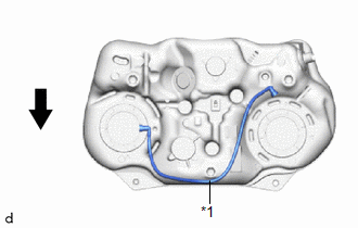
| *1 | Fuel Return Vent Tube Sub-assembly |
 | Front of the Vehicle |
- Make sure to correctly assemble the fuel return vent tube sub-assembly as shown in the illustration. If assembled incorrectly, the fuel sender gauge assembly (No. 2 fuel sender gauge assembly) may catch on the fuel return vent tube resulting in incorrect operation of the fuel sender gauge assembly (No. 2 fuel sender gauge assembly) and an incorrect value being displayed on the fuel gauge.
- When connecting the fuel tube connector, do not excessively pull on the fuel return vent tube sub-assembly.
- Be careful not to bend the arm of the No. 2 fuel sender gauge assembly.
3. INSTALL FUEL PUMP GAUGE RETAINER
HINT:
Perform the same procedure as for the fuel suction tube with pump and gauge assembly.
Click here

4. INSTALL NO. 1 FUEL TUBE CLAMP
Click here

5. INSTALL REAR FLOOR SERVICE HOLE COVER (for RH Side)
(a) Remove any remaining butyl tape from the rear floor service hole cover and body.
(b) Connect the connector to the fuel tank vent tube assembly.
(c) Install the rear floor service hole cover with new butyl tape.
NOTICE:
Securely install the rear floor service hole cover.
6. INSTALL FUEL SENDER GAUGE ASSEMBLY
(a) Attach the claw and install the fuel sender gauge assembly.
NOTICE:
Be careful not to bend the arm of the fuel sender gauge assembly.
(b) Connect the 2 connectors to the fuel suction plate sub-assembly.
(c) Attach the 3 clamps and connect the wire harness.
NOTICE:
Do not damage the wire harness.
7. INSTALL FUEL SUCTION WITH PUMP AND GAUGE TUBE ASSEMBLY
Click here

 Inspection
INSPECTION PROCEDURE 1. INSPECT FUEL SENDER GAUGE ASSEMBLY CAUTION: Perform the inspection in a well-ventilated area. Do not perform the inspection near an open flame...
 Fuel System
..
Other information:
Toyota Yaris XP210 (2020-2026) Reapir and Service Manual: Generator "A" Mechanical Performance Mechanical Failure (P065C07)
DESCRIPTION The alternator performs self-diagnosis of its internal circuits to detect malfunctions (open or short circuits). The ECM receives the result via LIN communication and stores a DTC. DTC No. Detection Item DTC Detection Condition Trouble Area MIL Note P065C07 Generator "A" Mechanical Performance Mechanical Failure All of the following conditions are met (1 trip detection logic): Engine running (except during engine cranking)...
Toyota Yaris XP210 (2020-2026) Reapir and Service Manual: Registration
REGISTRATION PROCEDURE 1. ECU EXCHANGE NOTICE: When replacing the engine stop and start ECU, make sure to download the number of starter operations (step 1). After replacing the engine stop and start ECU (step 2), write the number of starter operations to the new engine stop and start ECU (step 3)...
Categories
- Manuals Home
- Toyota Yaris Owners Manual
- Toyota Yaris Service Manual
- Removal
- Fuel Gauge
- How to use USB mode
- New on site
- Most important about car
Break-In Period
No special break-in is necessary, but a few precautions in the first 600 miles (1,000 km) may add to the performance, economy, and life of the vehicle.
Do not race the engine. Do not maintain one constant speed, either slow or fast, for a long period of time. Do not drive constantly at full-throttle or high engine rpm for extended periods of time. Avoid unnecessary hard stops. Avoid full-throttle starts.