Toyota Yaris: How To Troubleshoot Ecu Controlled Systems / How To Proceed With Troubleshooting
HOW TO PROCEED WITH TROUBLESHOOTING
OPERATION FLOW
HINT:
Perform troubleshooting in accordance with the procedure below. The following is an outline of basic troubleshooting procedure. Confirm the troubleshooting procedure for the circuit you are working on before beginning troubleshooting.
1.VEHICLE BROUGHT TO WORKSHOP
2.CUSTOMER PROBLEM ANALYSIS
(a) Ask the customer about the conditions and environment when the problem occurred.
3.INSPECT AUXILIARY BATTERY VOLTAGE
(a) Measure the auxiliary battery voltage.
Standard Voltage:
11 to 14 V (12V auxiliary battery)
18 to 27 V (24V auxiliary battery)
- If the voltage is below 11 V, recharge or replace the auxiliary battery before proceeding to the next step.
- If the voltage is below 18 V, recharge or replace the auxiliary battery before proceeding to the next step.
4.SYMPTOM CONFIRMATION AND DTC (AND FREEZE FRAME DATA) CHECK
(a) Visually check the wire harnesses, connectors and fuses for open and short circuits.
(b) Warm up the engine to the normal operating temperature.
(c) Confirm the problem symptoms and conditions, and check for DTCs.
| Result | Proceed to |
|---|---|
| DTCs are output | Go to step 5 |
| DTCs are not output | Go to step 6 |
5.DTC CHART
(a) Find the output DTC in the DTC chart. Look at the Trouble Area column for a list of potentially malfunctioning circuits and/or parts.
| Proceed to |
|---|
| Go to step 7 |
6.PROBLEM SYMPTOMS CHART
(a) Find the problem symptoms in the problem symptoms table. Look at the Suspected Area column for a list of potentially malfunctioning circuits and/or parts.
7.CIRCUIT INSPECTION OR PARTS INSPECTION
(a) Identify the malfunctioning circuit or part.
8.ADJUST, REPAIR OR REPLACE
(a) Adjust, repair or replace the malfunctioning circuit or parts.
9.CONFIRMATION TEST
(a) After the adjustment, repairs or replacement, check that the malfunction no longer exists. (If the malfunction is reoccurring, perform a confirmation test in the same environment and conditions as when the malfunction first occurred.)
(b) For malfunctions for which a DTC was output, check the DTC judgment result.
HINT:
-
The following information is displayed.
Techstream Display
Description
Test Failed
Shows the malfunction judgment results during the current trip.
Pending
Shows the malfunction judgment results up to now. (Indicates the possibility of a malfunction when no DTC is confirmed.)
Confirmed
Shows the DTCs confirmed up to now. (The number of current trips differs for each DTC.)
- Some systems do not support the checking of DTC judgment results.
CUSTOMER PROBLEM ANALYSIS
HINT:
- When troubleshooting, confirm that the problem symptoms have been accurately identified. Preconceptions should be discarded in order to make an accurate judgment. To clearly understand what the problem symptoms are, it is extremely important to ask the customer about the problem and the conditions at the time the malfunction occurred.
- Gather as much information as possible for reference. Past problems that seem unrelated may also help in some cases.
-
The following 5 items are important points for problem analysis:
What
Vehicle model, system name
When
Date, time, occurrence frequency
Where
Road conditions
Under what conditions?
Driving conditions, weather conditions
How did it happen?
Problem symptoms
SYMPTOM CONFIRMATION AND DIAGNOSTIC TROUBLE CODE
HINT:
The diagnostic system in this vehicle has various functions.
- The first function is the Diagnostic Trouble Code (DTC) check. A DTC is a code stored in the ECU memory whenever a malfunction in the signal circuits to the ECU occurs. In a DTC check, DTCs stored by a previous malfunction can be checked by a technician during troubleshooting.
-
Another function is the Input Signal Check, which checks if the signals from various switches are sent to the ECU correctly.
By using these functions, the problem areas can be narrowed down and troubleshooting can be more effective.
- In the DTC check, it is very important to determine whether the problem indicated by a DTC either: 1) still exists, or 2) occurred in the past but the vehicle has returned to normal. In addition, the DTC should be compared to any customer reported problem symptoms to see if they are related. For this reason, DTCs should be checked before and after confirmation of symptoms (i.e., whether or not problem symptoms exist) to determine current system conditions, as shown below.
- Never skip the DTC check. Failing to check for DTCs, depending on the case, may result in unnecessary troubleshooting for systems operating normally or lead to repairs not related to the problem. Follow the procedure listed below in the correct order.
- The following shows how to proceed with troubleshooting using the DTC check and will indicate how to proceed either to DTC troubleshooting or to the troubleshooting of each problem symptom.
1.DTC CHECK
HINT:
Check the timestamp.
- The order and time that DTCs were stored in the ECU can be checked from the timestamp (time at which the DTC occurred).
- When the main body ECU or central gateway ECU is replaced, the trip counter information of the newly replaced ECU is reflected.
- When the combination meter assembly is replaced, the total distance traveled of the newly replaced meter is reflected.
- Some systems do not support the checking of the timestamp.
2.MAKE A NOTE OF DTC DISPLAYED AND THEN CLEAR DTCs
HINT:
Some systems can clear the DTCs by removing the fuse.
3.SYMPTOM CONFIRMATION
| Result | Proceed to |
|---|---|
| No symptoms exist | Go to step 4 |
| Symptoms exist | Go to step 5 |
4.SIMULATION TEST USING SYMPTOM SIMULATION METHODS
5.DTC CHECK
| Result | Proceed to |
|---|---|
| DTCs are not output | Go to step 6 |
| DTCs are output | TROUBLESHOOT FOR PROBLEM INDICATED BY DTC |
6.SYMPTOM CONFIRMATION
| Result | Proceed to |
|---|---|
| Symptoms exist | TROUBLESHOOT FOR EACH PROBLEM SYMPTOM |
| No symptoms exist | END |
If a DTC was displayed in the initial DTC check, the problem may have occurred in a wire harness or connector in that circuit in the past. Check the wire harness and connectors.
If problem symptoms are present, but no DTCs were stored again after they were cleared, then the problem causing the symptom may be occurring for something that does not store DTCs (the DTC that was displayed in the initial DTC check may have been from a past problem or a secondary problem).
SYMPTOM SIMULATION
HINT:
The most difficult case in troubleshooting is when no problem symptoms occur. In such a case, a thorough problem analysis must be carried out. A simulation of the same or similar conditions and environment in which the problem occurred in the customer's vehicle should be carried out. No matter how much skill or experience a technician has, troubleshooting without confirming the problem symptoms will lead to important repairs being overlooked and mistakes or delays.
For example:
With a problem that only occurs when the engine is cold or as a result of vibration caused by the road during driving, the problem can never be determined if the symptoms are being checked on a stationary vehicle or a vehicle with a warmed-up engine. Vibration, heat or water penetration (moisture) is difficult to reproduce. The following symptom simulation tests are effective substitutes for the conditions and can be applied to a stationary vehicle. Important points in the symptom simulation test:
In the symptom simulation test, the problem symptoms as well as the problem area or parts must be confirmed. First, narrow down the possible problem circuits according to the symptoms. Then, connect the electrical tester and carry out the symptom simulation test, judging whether the circuit being tested is defective or normal. Also, confirm the problem symptoms at the same time. Refer to Problem Symptoms Table for each system to narrow down the possible causes.
To reproduce DTCs, it is necessary to satisfy the respective DTC detection conditions.
(a) VIBRATION METHOD: When a malfunction seems to occur as a result of vibration.
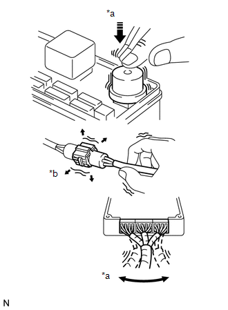
| *a | Vibrate Slightly |
| *b | Shake Slightly |
(1) PARTS OR SENSORS
Apply slight vibration with a finger to the part or sensor suspected to be the cause of the problem, and check whether the malfunction occurs.
NOTICE:
Applying strong vibration to relays may open the relays.
(2) CONNECTORS
Slightly shake the connector vertically and horizontally.
(3) WIRE HARNESS
Slightly shake the wire harness vertically and horizontally.
HINT:
The connector joint and fulcrum of the vibration are the major areas that should be checked thoroughly.
(b) HEAT METHOD: When a malfunction seems to occur when the area in question is heated.
(1) Heat the component that is the possible cause of the malfunction with a hair dryer or similar device. Check if the malfunction occurs.
NOTICE:
- Do not heat components to more than 60°C (140°F). Exceeding this temperature may damage the components.
- Do not apply heat directly to parts in an ECU.
(c) WATER SPRINKLING METHOD: When a malfunction seems to occur on a rainy day or in high-humidity.
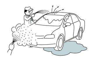
(1) Sprinkle water onto the vehicle and check if the malfunction occurs.
NOTICE:
- Never sprinkle water directly into the engine compartment. Indirectly change the temperature and humidity by spraying water onto the front of the radiator.
- Never apply water directly onto the electronic components.
HINT:
If the vehicle has or had a water leak problem, the leak may have damaged the ECU or connections. Look for evidence of corrosion or short circuits. Proceed with caution during water tests.
(d) HIGH ELECTRICAL LOAD METHOD: When a malfunction seems to occur when the electrical load is high.
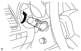
(1) Turn on the heater blower, headlights, rear window defogger and all other electrical loads. Check if the malfunction recurs.
DIAGNOSTIC TROUBLE CODE CHART
Look for output Diagnostic Trouble Codes (DTCs) (from the DTC checks) in the Diagnostic Trouble Code chart of the appropriate section. Use the chart to determine the trouble area and the proper inspection procedure. A description of each of the columns of the chart is shown in the table below.
| Item | Description |
|---|---|
| DTC No. | Indicates the diagnostic trouble code. |
| Detection Item | Indicates the system or details of the problem. |
| DTC Detection Condition | Indicates the condition in which a DTC is stored. |
| Trouble Area | Indicates the suspected areas of the problem. |
| Link | Indicates the page where the inspection procedure for each circuit is to be found, or gives instruction for checking and repair. |
PROBLEM SYMPTOMS TABLE
When no DTCs are output but the problem still occurs, use the Problem Symptoms Table. The suspected areas (circuits or parts) for each problem symptom are shown in the table. The suspected areas are listed in order of probability. A description of each of the table columns is shown in the following table.
HINT:
In some cases, the problem is not detected by the diagnostic system even though a problem symptom occurs. It is possible that the problem occurs outside the detection range of the diagnostic system, or that the problem occurs in a completely different system.
| Item | Description |
|---|---|
| Symptom | - |
| Suspected Area | Indicates the circuit or part which needs to be checked. |
| Link | Indicates the page where the inspection procedure is located. |
INSPECTION
A description of the main points for inspection of suspected areas is shown in the following table.
| Item | Description |
|---|---|
| Description | Explains the major role and operation of the circuit or system and its component parts. |
| DTC No., DTC Detection Condition and Trouble Area | Indicates the diagnostic trouble codes, DTC detection conditions and suspected areas for a problem. |
| Wiring Diagram | Indicates a wiring diagram for the circuit or system. This diagram can be used together with the Electrical Wiring Diagram to thoroughly understand the circuit. Wire colors are indicated by alphabetical codes. B = Black, L = Blue, R = Red, BR = Brown, LG = Light Green, V = Violet, G = Green, O = Orange, W = White, GR = Gray, P = Pink, Y = Yellow, SB = Sky Blue The first letter indicates the basic wire color and the second letter indicates the color of the stripe. |
| Procedure | Shows the procedure not only to determine whether the circuit is normal or abnormal, but also to determine whether the problem is located in the sensors, actuators, wire harness or ECU. |
| Illustration of the ECU connector during the check | Shows whether the connector being checked is connected or disconnected. The connections for an electrical tester are indicated by (+) or (-) after the terminal name. For inspections between a connector and body ground, information about the ground is not shown in the illustration. |
 Electronic Circuit Inspection Procedure
ELECTRONIC CIRCUIT INSPECTION PROCEDURE BASIC INSPECTION (a) WHEN MEASURING RESISTANCE OF ELECTRONIC PARTS (1) Unless otherwise stated, all resistance measurements are standard values measured at an ambient temperature of 20°C (68°F)...
 How To Use This Manual
General InformationGENERAL INFORMATION GENERAL DESCRIPTION (a) This manual is written in accordance with SAE J2008. (b) Repair operations can be separated mainly into the following 3 processes: (1) Diagnosis (2) Removing/Installing, Replacing, Disassembling/Reassembling, Checking and Adjusting (3) Final Inspection (c) The following procedures are omitted from this manual...
Other information:
Toyota Yaris XP210 (2020-2026) Reapir and Service Manual: Removal
REMOVAL CAUTION / NOTICE / HINT The necessary procedures (adjustment, calibration, initialization or registration) that must be performed after parts are removed and installed, or replaced during fuel injector assembly removal/installation are shown below...
Toyota Yaris XP210 (2020-2026) Reapir and Service Manual: All Door Entry Lock/Unlock Functions do not Operate, but Wireless Functions Operate
DESCRIPTION When the wireless operation can be used to lock and unlock the doors, communication between the smart door control receiver assembly and certification ECU (smart key ECU assembly) is normal. If the entry lock and unlock functions do not operate, the entry cancel function may be set through the customize function, there may be communication problems between the electrical key transmitter sub-assembly and vehicle, or there may be wave interference...
Categories
- Manuals Home
- Toyota Yaris Owners Manual
- Toyota Yaris Service Manual
- Adjustment
- Immobilizer System
- G16e-gts (engine Mechanical)
- New on site
- Most important about car
Break-In Period
No special break-in is necessary, but a few precautions in the first 600 miles (1,000 km) may add to the performance, economy, and life of the vehicle.
Do not race the engine. Do not maintain one constant speed, either slow or fast, for a long period of time. Do not drive constantly at full-throttle or high engine rpm for extended periods of time. Avoid unnecessary hard stops. Avoid full-throttle starts.