Toyota Yaris: Lighting System / Terminals Of Ecu
TERMINALS OF ECU
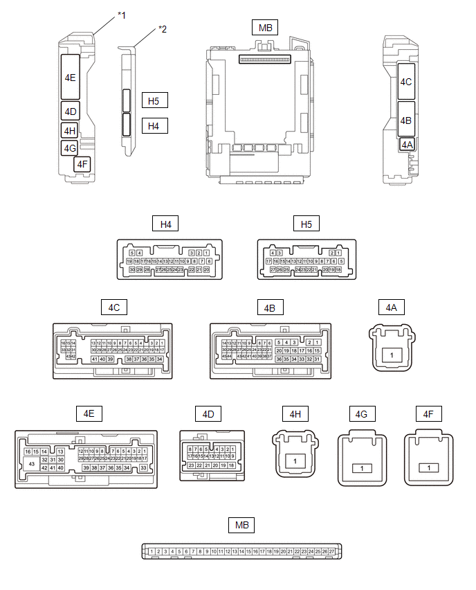
| *1 | Power Distribution Box Assembly | *2 | Main Body ECU (Multiplex Network Body ECU) |
CHECK MAIN BODY ECU (MULTIPLEX NETWORK BODY ECU) AND POWER DISTRIBUTION BOX ASSEMBLY
(a) Remove the main body ECU (multiplex network body ECU) from the power distribution box assembly.
Click here
.gif)
(b) Connect the power distribution box assembly connectors.
(c) Measure the voltage and resistance according to the value(s) in the table below.
| Terminal No. (Symbol) | Terminal Description | Condition | Specified Condition |
|---|---|---|---|
| MB-13 (GND1) - Body ground | Ground | Always | Below 1 Ω |
| MB-14 (GND2) - Body ground | Ground | Always | Below 1 Ω |
| MB-26 (BECU) - Body ground | Auxiliary battery power supply | Ignition switch off | 11 to 14 V |
| MB-27 (IGR) - Body ground | Ignition power supply | Ignition switch off | Below 1 Ω |
| Ignition switch ON | 11 to 14 V |
(d) Install the main body ECU (multiplex network body ECU).
Click here
(e) Connect the power distribution box assembly and main body ECU (multiplex network body ECU) connectors.
(f) Measure the voltage and resistance, and check for pulses according to the value(s) in the table below.
| Terminal No. (Symbol) | Terminal Description | Condition | Specified Condition |
|---|---|---|---|
| H4-26 (HEAD) - Body ground | Light control switch in HEAD position signal input | Light control switch not in HEAD position | 11 to 14 V |
| Light control switch in HEAD position | Below 1 V | ||
| 4D-10 - Body ground | Headlight assembly LH power supply | Ignition switch off | 11 to 14 V |
| Ignition switch ON | Below 1 V | ||
| 4D-6 - Body ground | Headlight assembly RH power supply | Ignition switch off | 11 to 14 V |
| Ignition switch ON | Below 1 V | ||
| H4-8 (CLTB) - H4-21 (CLTE) | Automatic light control sensor power supply output | Ignition switch off | Below 1 V |
| Ignition switch ON | 11 to 14 V | ||
| H4-14 (AHBI) - Body ground | Auto high beam switch signal input | Auto high beam switch on | Below 1 V |
| Auto high beam switch off | 11 to 14 V | ||
| H4-20 (CLTS) - Body ground | Automatic light control sensor signal input | Ignition switch ON | Pulse generation (See waveform 1) |
| 4E-5 - Body ground | Front door courtesy light switch assembly RH input | Front door RH open | 4.7 to 5.3 V |
| Front door RH closed | Below 1 V |
(1) Waveform 1
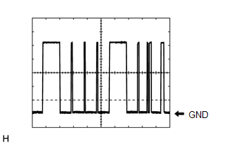
| Item | Content |
|---|---|
| Tester Connection | H4-20 (CLTS) - Body ground |
| Tool setting | 2 V/DIV., 10 ms./DIV. |
| Condition | Ignition switch ON |
HINT:
The communication waveform changes according to the surrounding brightness.
CHECK COMBINATION METER ASSEMBLY
Click here
CHECK STEERING SENSOR
Click here
CHECK FORWARD RECOGNITION CAMERA (w/ Toyota Safety Sense)
Click here
SEMICONDUCTOR POWER INTEGRATION ECU
Click here
 Problem Symptoms Table
PROBLEM SYMPTOMS TABLE NOTICE:
Before replacing the main body ECU (multiplex network body ECU), refer to Registration.
Click here
When replacing the combination meter assembly, always replace it with a new one...
 Dtc Check / Clear
DTC CHECK / CLEAR CHECK FOR DTC (MAIN BODY) (a) Check for DTCs. Body Electrical > Main Body > Trouble Codes CHECK FOR DTC (FRONT RECOGNITION CAMERA (FRONT LIGHTING CONTROL)) (a) Check for DTCs...
Other information:
Toyota Yaris XP210 (2020-2024) Reapir and Service Manual: Right Front Wheel Speed Sensor Signal Stuck Low (C050623)
DESCRIPTION Refer to DTC C05061F. Click here DTC No. Detection Item DTC Detection Condition Trouble Area DTC Output from C050623 Right Front Wheel Speed Sensor Signal Stuck Low Any of the following is detected: When the +BS terminal voltage is 17...
Toyota Yaris XP210 (2020-2024) Reapir and Service Manual: HO2S Heater Control Bank 1 Sensor 1 Circuit Short to Battery (P003012,P003013,P101A9E)
DESCRIPTION The air fuel ratio sensor (sensor 1) generates current that corresponds to the actual air fuel ratio. This sensor current is used to provide the ECM with feedback so that it can control the air fuel ratio. The ECM determines the deviation from the stoichiometric air fuel ratio level, and regulates the fuel injection duration...
Categories
- Manuals Home
- Toyota Yaris Owners Manual
- Toyota Yaris Service Manual
- Operating the Radio
- Fuse Panel Description
- Low Engine Coolant Temperature Indicator Light (Blue)
- New on site
- Most important about car
Supplemental Restraint System (SRS) Precautions
The front and side supplemental restraint systems (SRS) include different types of air bags. Please verify the different types of air bags which are equipped on your vehicle by locating the “SRS AIRBAG” location indicators. These indicators are visible in the area where the air bags are installed.
The air bags are installed in the following locations:
The steering wheel hub (driver air bag) The front passenger dashboard (front passenger air bag) The outboard sides of the front seatbacks (side air bags) The front and rear window pillars, and the roof edge along both sides (curtain air bags)