Toyota Yaris: Smart Key System (for Start Function) / System Diagram
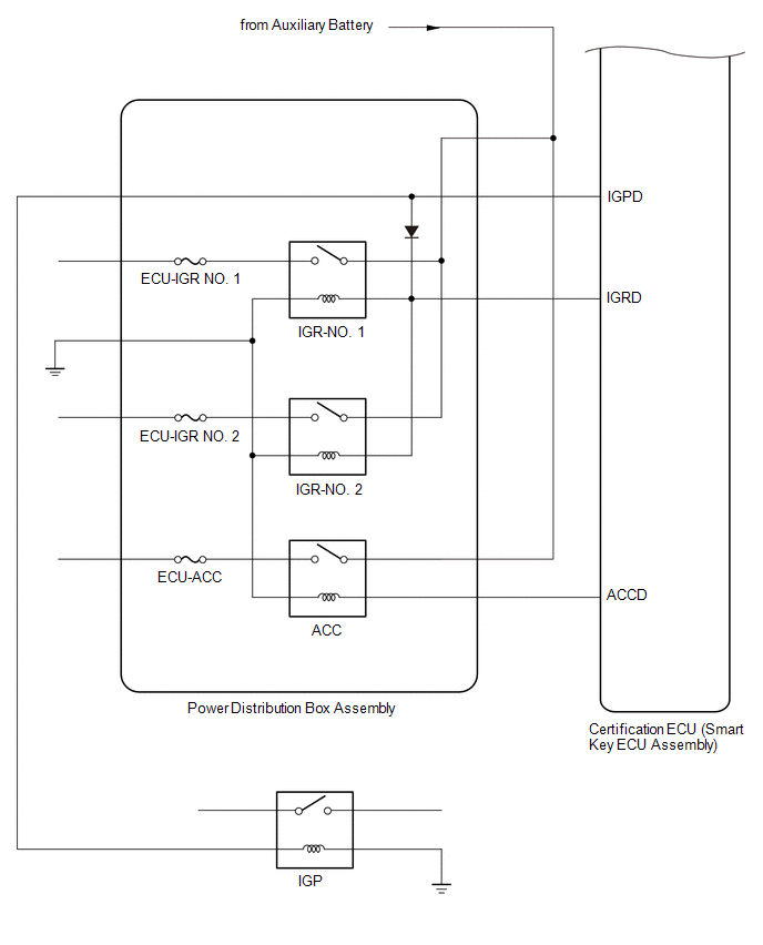
SYSTEM DIAGRAM
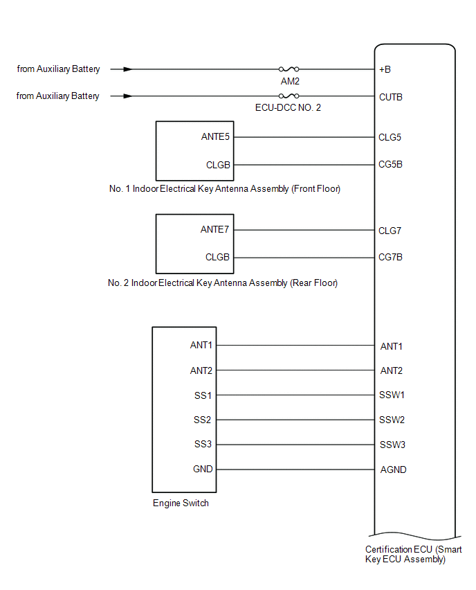
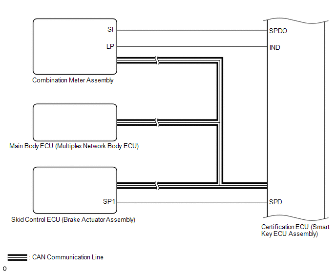
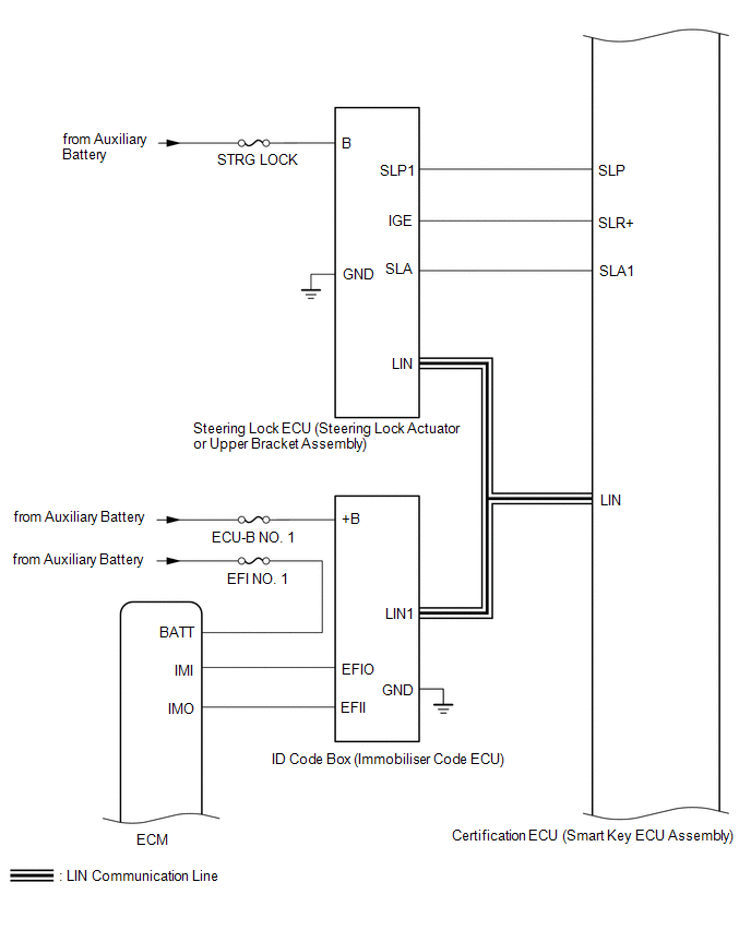
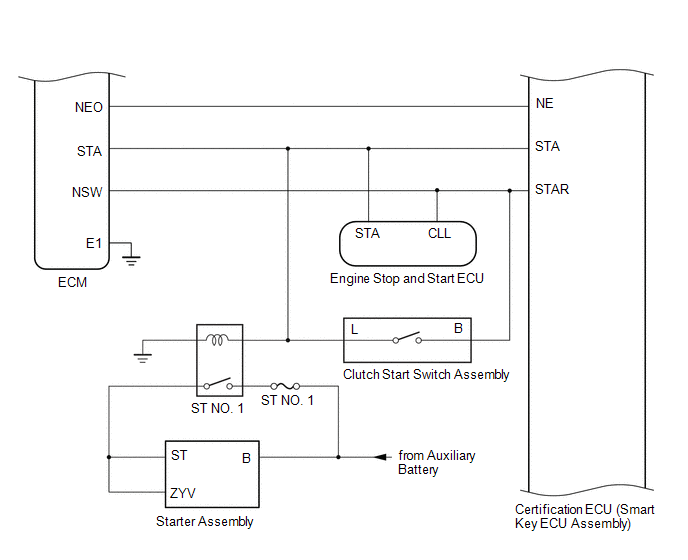
SMART KEY SYSTEM (for Start Function)
SMART KEY SYSTEM (for Entry Function)
Click here

 Parts Location
PARTS LOCATION ILLUSTRATION
*1 ECM *2 NO. 1 ENGINE ROOM RELAY BLOCK ASSEMBLY - ST NO. 1 FUSE - EFI NO. 1 FUSE - IGP RELAY - ST NO. 1 RELAY *3 SKID CONTROL ECU (BRAKE ACTUATOR ASSEMBLY) - - ILLUSTRATION
*1 NO...
 How To Proceed With Troubleshooting
CAUTION / NOTICE / HINT HINT:
Replace parts related to the wireless door lock control system and smart key system according to the inspection procedure...
Other information:
Toyota Yaris XP210 (2020-2024) Reapir and Service Manual: Lost Communication with Battery Monitor Module Missing Message (P162B87)
DESCRIPTION The ECM and battery state sensor assembly each detect reception malfunctions. A battery state sensor assembly reception malfunction detected by the battery state sensor assembly is sent to the ECM via LIN communication. If there is a malfunction in either the ECM or battery state sensor assembly, the ECM determines that there is a LIN communication malfunction and outputs a DTC...
Toyota Yaris XP210 (2020-2024) Reapir and Service Manual: Installation
INSTALLATION CAUTION / NOTICE / HINT HINT: Use the same procedure for the RH side and LH side. The following procedure is for the LH side. PROCEDURE 1. INSTALL REAR DISC BRAKE ANTI SQUEAL SHIM KIT (a) Install the 2 rear disc brake anti-squeal shims to each rear disc brake pad...
Categories
- Manuals Home
- Toyota Yaris Owners Manual
- Toyota Yaris Service Manual
- Fuse Panel Description
- Headlights
- Adjustment
- New on site
- Most important about car
Refueling
Before refueling, close all the doors, windows, and the liftgate/trunk lid, and switch the ignition OFF.
To open the fuel-filler lid, pull the remote fuel-filler lid release.

Copyright © 2024 www.toyaris4.com