Toyota Yaris: Smart Key System (for Start Function) / Parts Location
PARTS LOCATION
ILLUSTRATION
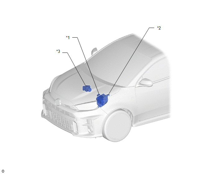
| *1 | ECM | *2 | NO. 1 ENGINE ROOM RELAY BLOCK ASSEMBLY - ST NO. 1 FUSE - EFI NO. 1 FUSE - IGP RELAY - ST NO. 1 RELAY |
| *3 | SKID CONTROL ECU (BRAKE ACTUATOR ASSEMBLY) | - | - |
ILLUSTRATION
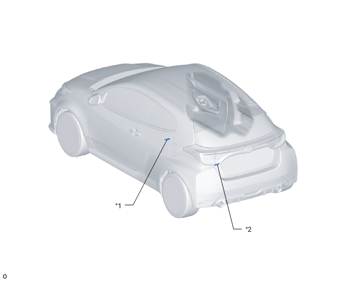
| *1 | NO. 1 INDOOR ELECTRICAL KEY ANTENNA ASSEMBLY (FRONT FLOOR) | *2 | NO. 2 INDOOR ELECTRICAL KEY ANTENNA ASSEMBLY (REAR FLOOR) |
ILLUSTRATION
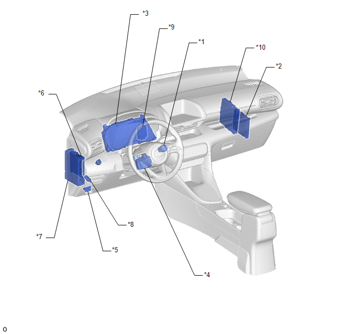
| *1 | ENGINE SWITCH | *2 | CERTIFICATION ECU (SMART KEY ECU ASSEMBLY) |
| *3 | COMBINATION METER ASSEMBLY - SECURITY INDICATOR LIGHT | *4 | STEERING LOCK ECU (STEERING LOCK ACTUATOR OR UPPER BRACKET ASSEMBLY) |
| *5 | DLC3 | *6 | MAIN BODY ECU (MULTIPLEX NETWORK BODY ECU) |
| *7 | POWER DISTRIBUTION BOX ASSEMBLY - STOP FUSE - STRG LOCK FUSE - AM2 FUSE - ECU-DCC NO. 2 FUSE - ECU-ACC FUSE - ECU-IGR NO. 1 FUSE - ECU-IGR NO. 2 FUSE - ECU-B NO. 1 FUSE - ACC RELAY - IGR-NO. 1 RELAY - IGR-NO. 2 RELAY | *8 | CLUTCH START SWITCH ASSEMBLY |
| *9 | ID CODE BOX (IMMOBILISER CODE ECU) | *10 | ENGINE STOP AND START ECU |
 Precaution
PRECAUTION CAUTION REGARDING INTERFERENCE WITH ELECTRONIC DEVICES CAUTION: As weak radio waves are emitted from the electrical key transmitter sub-assembly, if a pacemaker is being used, be sure to read the pacemaker instruction manual and the following...
 System Diagram
S..
Other information:
Toyota Yaris XP210 (2020-2024) Reapir and Service Manual: Installation
INSTALLATION CAUTION / NOTICE / HINT HINT: Use the same procedure for the RH side and LH side. The following procedure is for the LH side. PROCEDURE 1. INSTALL FRONT DOOR GLASS OUTER WEATHERSTRIP ASSEMBLY (a) Engage the claws to install a new front door glass outer weatherstrip assembly as shown in the illustration...
Toyota Yaris XP210 (2020-2024) Reapir and Service Manual: On-vehicle Inspection
ON-VEHICLE INSPECTION PROCEDURE 1. INSPECT AUTOMATIC LIGHT CONTROL SENSOR (a) Check the wire harness. (1) Disconnect the automatic light control sensor. (2) Measure the voltage according to the value(s) in the table below. Standard Voltage: Tester Connection Switch Condition Specified Condition H78-1 (CLTB) - H78-2 (CLTE) Ignition switch on (IG) 11 to 14 V If the specified condition is not met, replace the vehicle wire harness...
Categories
- Manuals Home
- Toyota Yaris Owners Manual
- Toyota Yaris Service Manual
- Brake System Control Module "A" System Voltage System Voltage Low (C137BA2)
- Diagnostic Trouble Code Chart
- Key Battery Replacement
- New on site
- Most important about car
Liftgate/Trunk Lid
WARNING
Never allow a person to ride in the luggage compartment/trunk
Allowing a person to ride in the luggage compartment/trunk is dangerous. The person in the luggage compartment/trunk could be seriously injured or killed during sudden braking or a collision.
Do not drive with the liftgate/trunk lid open