Toyota Yaris: Air Fuel Ratio Sensor (for Sensor 2) / Removal
REMOVAL
CAUTION / NOTICE / HINT
The necessary procedures (adjustment, calibration, initialization, or registration) that must be performed after parts are removed, installed, or replaced during the No. 2 air fuel ratio sensor removal/installation are shown below.
Necessary Procedure After Parts Removed/Installed/Replaced| Replacement Part or Procedure | Necessary Procedure | Effect/Inoperative when not Performed | Link |
|---|---|---|---|
| Inspection after repair |
|
|

CAUTION:
-
When the engine is hot, do not touch high-temperature areas such as the engine or exhaust pipe.
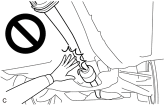
- Touching high-temperature areas such as the engine and exhaust pipe could result in burns.
PROCEDURE
1. REMOVE CENTER NO. 4 ENGINE UNDER COVER
Click here

2. REMOVE CENTER FRONT FLOOR BRACE
Click here

3. REMOVE CENTER NO. 1 FLOOR BRACE
Click here

4. REMOVE NO. 2 AIR FUEL RATIO SENSOR
| (a) Disconnect the No. 2 air fuel ratio sensor connector. |
|
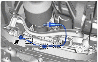
(b) Disengage the 3 wire harness clamps.
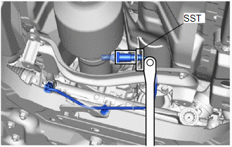
| (c) Using SST, remove the No. 2 air fuel ratio sensor from the front exhaust pipe assembly. SST: 09224-00012 NOTICE: If the No. 2 air fuel ratio sensor has been struck or dropped, replace it. |
|
 Components
COMPONENTS ILLUSTRATION
*1 NO. 2 AIR FUEL RATIO SENSOR *2 CENTER NO. 1 FLOOR BRACE *3 CENTER FRONT FLOOR BRACE *4 CENTER NO. 4 ENGINE UNDER COVER
N*m (kgf*cm, ft...
 Inspection
INSPECTION PROCEDURE 1. INSPECT NO. 2 AIR FUEL RATIO SENSOR (a) Measure the resistance according to the value(s) in the table below. Standard Resistance: Tester Connection Condition Specified Condition D109-1(HA1B) - D109-2(+B) 20°C (68°F) 1...
Other information:
Toyota Yaris XP210 (2020-2024) Reapir and Service Manual: Inspection
INSPECTION PROCEDURE 1. INSPECT OIL PRESSURE AND TEMPERATURE SENSOR (a) Check the oil pressure and temperature sensor output voltage. (1) Apply 5 V between terminals 3 (VC) and 2 (GND). NOTICE: Be careful when connecting the leads as the oil pressure and temperature sensor may be damaged if the leads are connected to the wrong terminals...
Toyota Yaris XP210 (2020-2024) Reapir and Service Manual: Problem Symptoms Table
PROBLEM SYMPTOMS TABLE NOTICE: If the main body ECU (multiplex network body ECU) is replaced, refer to the Registration. Click here HINT: Use the table below to help determine the cause of problem symptoms. If multiple suspected areas are listed, the potential causes of the symptoms are listed in order of probability in the "Suspected Area" column of the table...
Categories
- Manuals Home
- Toyota Yaris Owners Manual
- Toyota Yaris Service Manual
- How to use USB mode
- To Set Speed
- Speedometer, Odometer, Trip Meter and Trip Meter Selector
- New on site
- Most important about car
Fuel Gauge
The fuel gauge shows approximately how much fuel is remaining in the tank when the ignition is switched ON. We recommend keeping the tank over 1/4 full.
