Toyota Yaris: Active Noise Control System / Power Source Circuit
DESCRIPTION
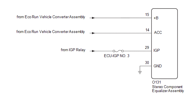
This circuit is the power source circuit for the stereo component equalizer assembly.
WIRING DIAGRAM
CAUTION / NOTICE / HINT
NOTICE:
Inspect the fuses and relays for circuits related to this system before performing the following procedure.
PROCEDURE
| 1. | CHECK HARNESS AND CONNECTOR (STEREO COMPONENT EQUALIZER ASSEMBLY POWER SOURCE) |
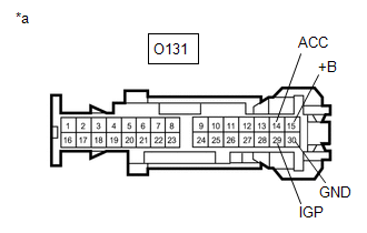
| (a) Disconnect the O131 stereo component equalizer assembly connector. |
|
(b) Measure the voltage according to the value(s) in the table below.
Standard Voltage:
| Tester Connection | Condition | Specified Condition |
|---|---|---|
| O131-15 (+B) - Body ground | Ignition switch off | 10.5 to 16 V |
| O131-29 (IGP) - Body ground | Ignition switch ON | 11 to 14 V |
| O131-14 (ACC) - Body ground | Ignition switch ACC | 10.5 to 16 V |
(c) Measure the resistance according to the value(s) in the table below.
Standard Resistance:
| Tester Connection | Condition | Specified Condition |
|---|---|---|
| O131-30 (GND) - Body ground | Always | Below 1 Ω |
| Result | Proceed to |
|---|---|
| OK | A |
| NG (except IGP circuit) | B |
| NG (for IGP circuit) | C |
| A |
 | PROCEED TO NEXT SUSPECTED AREA SHOWN IN PROBLEM SYMPTOMS TABLE |
| B |
 | GO TO STOP AND START SYSTEM |
| C |
 | REPAIR OR REPLACE HARNESS OR CONNECTOR |
 Crankshaft Position Sensor "A" No Signal (P033531)
DESCRIPTION This DTC is output when a malfunction has occurred in the engine pulse signal system from the ECM. DTC No. Detection Item DTC Detection Condition Trouble Area P033531 Crankshaft Position Sensor "A" No Signal Stereo component equalizer assembly detects malfunction in engine pulse signal system for 10 seconds or more continuously when engine speed is between 500 and 6000 rpm*
Harness or connector
ECM
Stereo component equalizer assembly
HINT: *: Malfunction monitoring is not performed under the following conditions, in order to prevent erroneous detection...
 Lost Communication With ECM/PCM "A" Missing Message (U010087,U012987,U014087)
DESCRIPTION These DTCs are stored when a malfunction occurs in the CAN communication circuit. DTC No. Detection Item DTC Detection Condition Trouble Area U010087 Lost Communication With ECM/PCM "A" Missing Message When the stereo component equalizer assembly detects a CAN communication malfunction in the engine system for 1 second or more continuously 3 seconds after the ignition switch is turned to ON* CAN communication system U012987 Lost Communication With Brake System Control Module Missing Message When the stereo component equalizer assembly detects a CAN communication malfunction in the brake system for 1 second or more continuously 3 seconds after the ignition switch is turned to ON* CAN communication system U014087 Lost Communication with Body Control Module Missing Message When the stereo component equalizer assembly detects a CAN communication malfunction in the main body ECU for 3 seconds or more continuously 3 seconds after the ignition switch is turned to ON* CAN communication system HINT: *: Malfunction monitoring is not performed under the following conditions, in order to prevent erroneous detection...
Other information:
Toyota Yaris XP210 (2020-2024) Reapir and Service Manual: Diagnosis System
DIAGNOSIS SYSTEM EURO-OBD (EUROPEAN SPEC) (a) When troubleshooting Europe On-Board Diagnostic (Euro-OBD) vehicles, an OBD scan tool (complying with ISO 15765-4) must be connected to the vehicle. Various data output from the vehicle's ECM can then be read...
Toyota Yaris XP210 (2020-2024) Reapir and Service Manual: How To Connect Or Disconnect Airbag Connector
HOW TO CONNECT OR DISCONNECT AIRBAG CONNECTOR PROCEDURE 1. TYPES OF AIRBAG CONNECTOR (a) Types of Connector TYPE Shape (Example) Pull Up Type 2-Step Lock Type Slide Lock Type 2. DISCONNECT OR CONNECT AIRBAG CONNECTOR (for Pull Up Type) (a) Disconnect the connector...
Categories
- Manuals Home
- Toyota Yaris Owners Manual
- Toyota Yaris Service Manual
- Key Battery Replacement
- Adjustment
- Operating the Radio
- New on site
- Most important about car
Refueling
Before refueling, close all the doors, windows, and the liftgate/trunk lid, and switch the ignition OFF.
To open the fuel-filler lid, pull the remote fuel-filler lid release.
