Toyota Yaris: Vehicle Stability Control System / Zero Point Calibration of Steering Angle Sensor Malfunction (X20D7)
DESCRIPTION
| Code | Tester Display | Measurement Item | Trouble Area | RoB Output from |
|---|---|---|---|---|
| X20D7 | Zero Point Calibration of Steering Angle Sensor Malfunction | History of the steering angle sensor zero point calibration position differing from the stored value |
| Brake |
CAUTION / NOTICE / HINT
NOTICE:
After performing the inspection, check and clear the vehicle control history (RoB).
PROCEDURE
| 1. | CHECK FOR DTCs (HEALTH CHECK) |
(a) Using the GTS, perform the Health Check.
| Result | Proceed to |
|---|---|
| DTCs are not output | A |
| DTCs are output | B |
| B |
 | GO TO DIAGNOSTIC TROUBLE CODE CHART |
|
| 2. | CLEAR VEHICLE CONTROL HISTORY (RoB) |
(a) Using the GTS, clear the Vehicle Control History (RoB).
Chassis > Brake > Utility| Tester Display |
|---|
| Vehicle Control History (RoB) |
|
| 3. | PERFORM ZERO POINT CALIBRATION OF YAW RATE AND ACCELERATION SENSOR |
(a) Perform zero point calibration of the yaw rate and acceleration sensor.
Chassis > Brake > Utility| Tester Display |
|---|
| Reset Memory |
| Tester Display |
|---|
| Calibration |
|
| 4. | CHECK STEERING ANGLE SENSOR ZERO POINT CALIBRATION |
(a) Drive the vehicle straight ahead at 35 km/h (22 mph) or more for at least 5 seconds.
(b) Drive the vehicle straight ahead at 15 km/h (9 mph) or more for at least 60 seconds.
(c) Check that the centered position of the steering wheel is correctly set while driving straight ahead.
Standard:
The steering wheel is centered correctly.
| NG |
 | GO TO STEP 7 |
|
| 5. | INSPECT STEERING SYSTEM |
(a) Perform the steering system on-vehicle inspection.
Click here

| OK |
 | USE SIMULATION METHOD TO CHECK |
|
| 6. | REPAIR OR REPLACE MALFUNCTIONING PART |
| NEXT |
 | GO TO STEP 8 |
| 7. | ADJUST WHEEL ALIGNMENT |
(a) Adjust the alignment (toe) of the wheels.
for front wheel alignment: Click here

for rear wheel alignment: Click here

|
| 8. | CLEAR VEHICLE CONTROL HISTORY (RoB) |
(a) Using the GTS, clear the Vehicle Control History (RoB).
Chassis > Brake > Utility| Tester Display |
|---|
| Vehicle Control History (RoB) |
|
| 9. | PERFORM ZERO POINT CALIBRATION OF YAW RATE AND ACCELERATION SENSOR |
(a) Perform zero point calibration of the yaw rate and acceleration sensor.
Chassis > Brake > Utility| Tester Display |
|---|
| Reset Memory |
| Tester Display |
|---|
| Calibration |
|
| 10. | PERFORM ZERO POINT CALIBRATION OF STEERING ANGLE SENSOR |
(a) Drive the vehicle straight ahead at 35 km/h (22 mph) or more for at least 5 seconds.
(b) Drive the vehicle straight ahead at 15 km/h (9 mph) or more for at least 60 seconds.
|
| 11. | CHECK VEHICLE CONTROL HISTORY (RoB) |
(a) Perform a road test under the same malfunction conditions recreated based on the Freeze Frame Data or customer problem analysis.
(b) Using the GTS, check for Vehicle Control History (RoB).
Chassis > Brake > Utility| Tester Display |
|---|
| Vehicle Control History (RoB) |
| Result | Proceed to |
|---|---|
| Vehicle Control History (RoB) is not output | A |
| Vehicle Control History (RoB) is output | B |
| A |
 | END |
| B |
 | GO TO VEHICLE CONTROL HISTORY |
 Zero Point Calibration of Yaw Rate Sensor Undone (X204C)
DESCRIPTION Code Tester Display Measurement Item Trouble Area RoB Output from X204C Zero Point Calibration of Yaw Rate Sensor Undone History of incomplete yaw rate sensor zero point calibration
Sensor installation
Yaw rate and acceleration sensor (airbag sensor assembly)
Brake CAUTION / NOTICE / HINT NOTICE:
After replacing the skid control ECU (brake actuator assembly), perform "Calibration"...
 TRC does not Operate
DESCRIPTION When TRC or VSC is operating, the skid control ECU (brake actuator assembly) blinks the slip indicator light to inform the driver that slippage occurred...
Other information:
Toyota Yaris XP210 (2020-2024) Reapir and Service Manual: Precaution
PRECAUTION CAUTION REGARDING INTERFERENCE WITH ELECTRONIC DEVICES CAUTION: As weak radio waves are emitted from the electrical key transmitter sub-assembly, if a pacemaker is being used, be sure to read the pacemaker instruction manual and the following...
Toyota Yaris XP210 (2020-2024) Reapir and Service Manual: Check Mode Procedure
CHECK MODE PROCEDURE HINT: Compared to normal mode, check mode is more sensitive to malfunctions. Therefore, check mode can detect malfunctions that cannot be detected in normal mode. NOTICE: All the stored DTCs and freeze frame data are cleared if: 1) the engine stop and start ECU is switched from normal mode to check mode or vice versa; or 2) the ignition switch is turned from ON to ACC or off while in check mode...
Categories
- Manuals Home
- Toyota Yaris Owners Manual
- Toyota Yaris Service Manual
- Low Engine Coolant Temperature Indicator Light (Blue)
- Fuse Panel Description
- Immobilizer System
- New on site
- Most important about car
Refueling
Before refueling, close all the doors, windows, and the liftgate/trunk lid, and switch the ignition OFF.
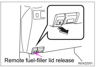
To open the fuel-filler lid, pull the remote fuel-filler lid release.


