Toyota Yaris: Meter / Gauge System / Tachometer Malfunction
DESCRIPTION
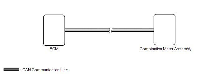
In this circuit, the combination meter assembly receives engine speed signals from the ECM via CAN communication. The combination meter assembly displays the engine speed calculated based on the data received from the ECM.
WIRING DIAGRAM
CAUTION / NOTICE / HINT
NOTICE:
- When replacing the combination meter assembly, always replace it with a new one. If a combination meter assembly which was installed to another vehicle is used, the information stored in it will not match the information from the vehicle and a DTC may be stored.
-
Before replacing the ECM, refer to Registration.
Click here

PROCEDURE
| 1. | CHECK CAN COMMUNICATION SYSTEM |
(a) Check if CAN communication DTCs are output.
Click here

| Result | Proceed to |
|---|---|
| DTCs are not output | A |
| DTCs are output | B |
| B |
 | GO TO CAN COMMUNICATION SYSTEM |
|

| 2. | CHECK FOR DTC (SFI SYSTEM) |
(a) Check if SFI system DTCs are output.
Powertrain > Engine > Trouble Codes| Result | Proceed to |
|---|---|
| DTCs are not output | A |
| DTCs are output | B |
| B |
 | GO TO SFI SYSTEM |
|

| 3. | PERFORM ACTIVE TEST USING GTS |
(a) Perform the Active Test according to the display on the GTS.
Body Electrical > Combination Meter > Active Test| Tester Display | Measurement Item | Control Range | Diagnostic Note |
|---|---|---|---|
| TachoMeter Operation (0rpm) | Tachometer (0 rpm) | ON | - |
| TachoMeter Operation (1000rpm) | Tachometer (1000 rpm) | ON | - |
| TachoMeter Operation (2000rpm) | Tachometer (2000 rpm) | ON | - |
| TachoMeter Operation (3000rpm) | Tachometer (3000 rpm) | ON | - |
| TachoMeter Operation (4000rpm) | Tachometer (4000 rpm) | ON | - |
| TachoMeter Operation (5000rpm) | Tachometer (5000 rpm) | ON | - |
| TachoMeter Operation (6000rpm) | Tachometer (6000 rpm) | ON | - |
| TachoMeter Operation (7000rpm) | Tachometer (7000 rpm) | ON | - |
| TachoMeter Operation (8000rpm) | Tachometer (8000 rpm) | ON | - |
| Tester Display |
|---|
| TachoMeter Operation (0rpm) |
| Tester Display |
|---|
| TachoMeter Operation (1000rpm) |
| Tester Display |
|---|
| TachoMeter Operation (2000rpm) |
| Tester Display |
|---|
| TachoMeter Operation (3000rpm) |
| Tester Display |
|---|
| TachoMeter Operation (4000rpm) |
| Tester Display |
|---|
| TachoMeter Operation (5000rpm) |
| Tester Display |
|---|
| TachoMeter Operation (6000rpm) |
| Tester Display |
|---|
| TachoMeter Operation (7000rpm) |
| Tester Display |
|---|
| TachoMeter Operation (8000rpm) |
OK:
Tachometer indication is normal.
| OK |
 | REPLACE ECM |
| NG |
 | REPLACE COMBINATION METER ASSEMBLY |
 Speedometer Malfunction
DESCRIPTION The combination meter assembly receives vehicle speed signals from the skid control ECU (brake actuator assembly) via CAN communication. The speed sensor detects the wheel speed and sends the appropriate signals to the skid control ECU (brake actuator assembly)...
 Fuel Receiver Gauge Malfunction
DESCRIPTION FUEL RECEIVER GAUGE OPERATION (a) OPERATION The combination meter assembly uses the fuel sender gauge assembly to detect the amount of fuel remaining in the fuel tank assembly...
Other information:
Toyota Yaris XP210 (2020-2024) Reapir and Service Manual: Terminals Of Ecu
TERMINALS OF ECU CHECK MAIN BODY ECU (MULTIPLEX NETWORK BODY ECU) AND POWER DISTRIBUTION BOX ASSEMBLY *1 Power Distribution Box Assembly *2 Main Body ECU (Multiplex Network Body ECU) (a) Remove the main body ECU (multiplex network body ECU) from the power distribution box assembly...
Toyota Yaris XP210 (2020-2024) Owner's Manual: Fog Lights
Use this switch to turn on the fog lights. The fog lights will improve visibility at night and during foggy conditions. The fog lights can be used when the ignition is switched ON. The fog lights turn on when the fog light switch is turned to the position and turn off when the switch is turned to the OFF position...
Categories
- Manuals Home
- Toyota Yaris Owners Manual
- Toyota Yaris Service Manual
- Speedometer, Odometer, Trip Meter and Trip Meter Selector
- Low Engine Coolant Temperature Indicator Light (Blue)
- Headlights
- New on site
- Most important about car
Supplemental Restraint System (SRS) Precautions
The front and side supplemental restraint systems (SRS) include different types of air bags. Please verify the different types of air bags which are equipped on your vehicle by locating the “SRS AIRBAG” location indicators. These indicators are visible in the area where the air bags are installed.
The air bags are installed in the following locations:
The steering wheel hub (driver air bag) The front passenger dashboard (front passenger air bag) The outboard sides of the front seatbacks (side air bags) The front and rear window pillars, and the roof edge along both sides (curtain air bags)