Toyota Yaris: Meter / Gauge System / System Diagram
SYSTEM DIAGRAM
HINT:
Refer to System Diagram of CAN Communication System.
Click here

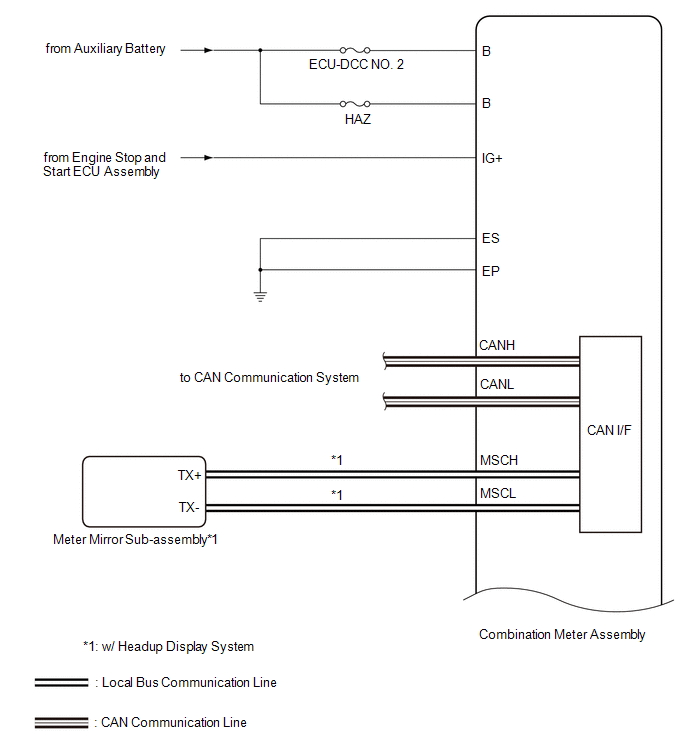
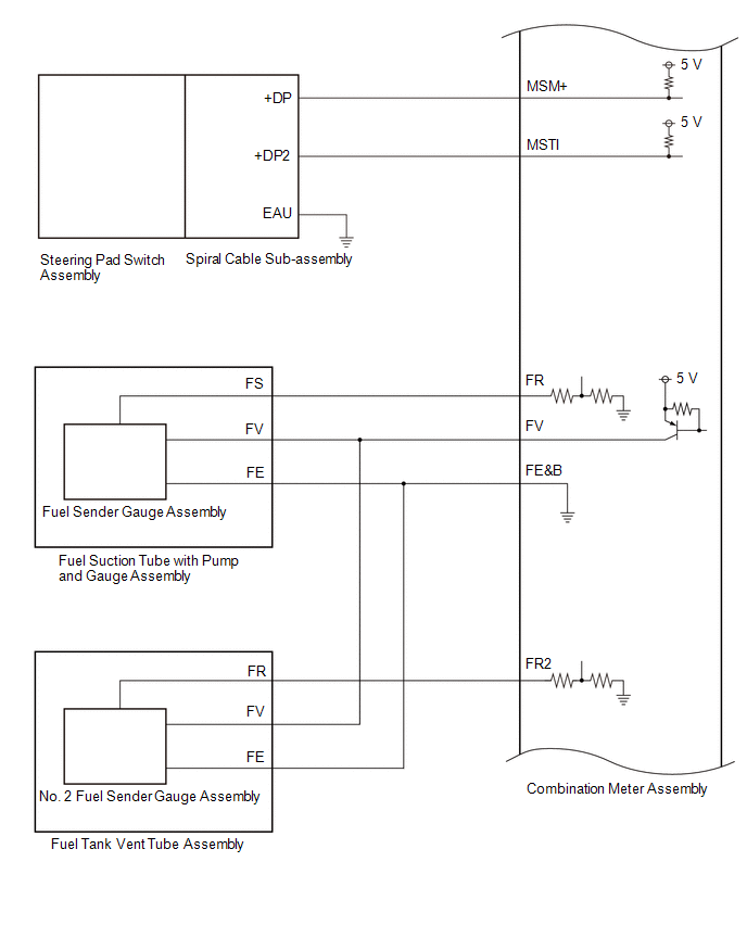
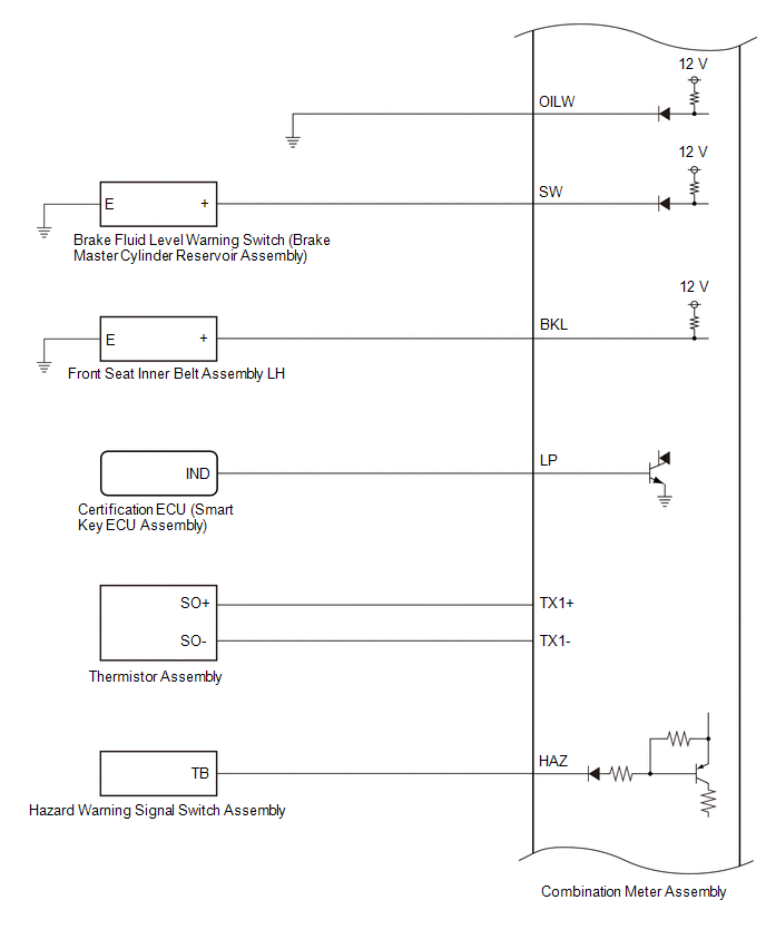
COMBINATION METER ASSEMBLY DIAGRAM
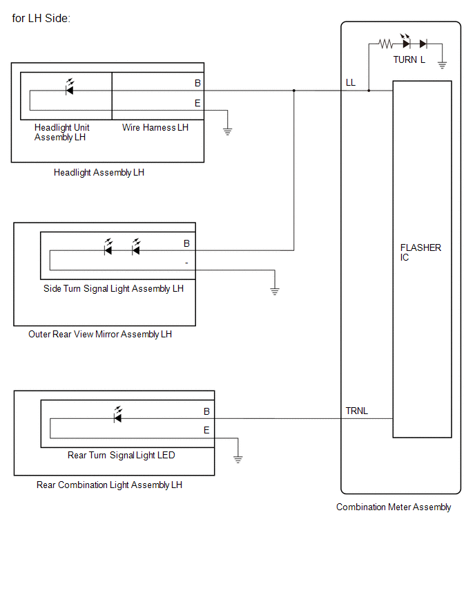
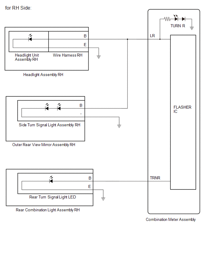
TURN SIGNAL LIGHT DIAGRAM
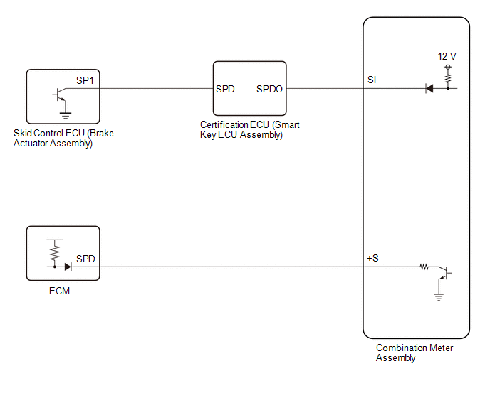
SPEED SIGNAL DIAGRAM
 Parts Location
PARTS LOCATION ILLUSTRATION
*1 BRAKE MASTER CYLINDER RESERVOIR ASSEMBLY - BRAKE FLUID LEVEL WARNING SWITCH *2 THERMISTOR ASSEMBLY *3 ECM *4 BRAKE ACTUATOR ASSEMBLY - SKID CONTROL ECU ILLUSTRATION
*1 HEADLIGHT ASSEMBLY RH *2 HEADLIGHT ASSEMBLY LH *3 HEADLIGHT UNIT ASSEMBLY RH *4 HEADLIGHT UNIT ASSEMBLY LH *5 HEADLIGHT CORD *6 OUTER REAR VIEW MIRROR ASSEMBLY RH - SIDE TURN SIGNAL LIGHT ASSEMBLY RH *7 OUTER REAR VIEW MIRROR ASSEMBLY LH - SIDE TURN SIGNAL LIGHT ASSEMBLY LH *8 REAR COMBINATION LIGHT ASSEMBLY RH *9 REAR COMBINATION LIGHT ASSEMBLY LH *10 REAR TURN SIGNAL LIGHT LED ILLUSTRATION
*1 MAIN BODY ECU (MULTIPLEX NETWORK BODY ECU) *2 POWER DISTRIBUTION BOX ASSEMBLY - ECU-DCC NO...
 How To Proceed With Troubleshooting
CAUTION / NOTICE / HINT HINT:
Use the following procedure to troubleshoot the meter / gauge system.
*: Use the GTS.
PROCEDURE 1. VEHICLE BROUGHT TO WORKSHOP
NEXT
2...
Other information:
Toyota Yaris XP210 (2020-2024) Reapir and Service Manual: Components
COMPONENTS ILLUSTRATION *1 FUEL PRESSURE SENSOR *2 NO. 1 FUEL PRESSURE SENSOR HOLDER *3 NO. 1 ENGINE COVER SUB-ASSEMBLY - - Tightening torque for "Major areas involving basic vehicle performance such as moving/turning/stopping": N*m (kgf*cm, ft...
Toyota Yaris XP210 (2020-2024) Reapir and Service Manual: Components
COMPONENTS ILLUSTRATION *1 NO. 1 ENGINE UNDER COVER ASSEMBLY - - N*m (kgf*cm, ft.*lbf): Specified torque - - ILLUSTRATION *1 NO. 1 ENGINE COVER SUB-ASSEMBLY *2 FUEL TUBE SUB-ASSEMBLY *3 NO. 1 FUEL VAPOR FEED HOSE *4 ENGINE WIRE *5 OUTLET HEATER WATER HOSE *6 NO...
Categories
- Manuals Home
- Toyota Yaris Owners Manual
- Toyota Yaris Service Manual
- Diagnostic Trouble Code Chart
- Key Battery Replacement
- Fuse Panel Description
- New on site
- Most important about car
Liftgate/Trunk Lid
WARNING
Never allow a person to ride in the luggage compartment/trunk
Allowing a person to ride in the luggage compartment/trunk is dangerous. The person in the luggage compartment/trunk could be seriously injured or killed during sudden braking or a collision.
Do not drive with the liftgate/trunk lid open
Copyright © 2024 www.toyaris4.com