Toyota Yaris: Exterior Panels / Trim / Rocker Panel Moulding
Components
COMPONENTS
ILLUSTRATION
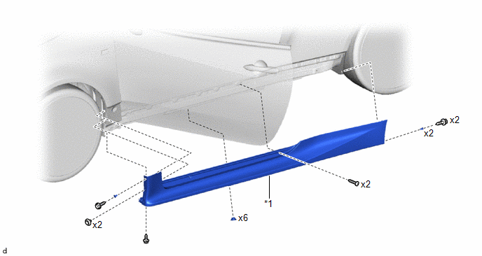
| *1 | ROCKER PANEL MOULDING | - | - |
Removal
REMOVAL
CAUTION / NOTICE / HINT
HINT:
- Use the same procedure for the RH side and LH side.
- The following procedure is for the LH side.
PROCEDURE
1. REMOVE REAR WHEEL HOUSE FRONT PLATE
Click here
.gif)
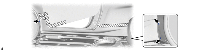
2. REMOVE ROCKER PANEL MOULDING
(a) Apply protective tape around the rocker panel moulding and front door panel as shown in the illustration.

.png) | Protective Tape | - | - |
(b) Remove the 6 clips.

(c) Remove the 2 clips and 6 screws.

(d) Remove the 3 grommets.
(e) Disengage the clips to remove the rocker panel moulding as shown in the illustration.
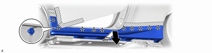
.png) | Remove in this Direction | - | - |
Installation
INSTALLATION
CAUTION / NOTICE / HINT
HINT:
- Use the same procedure for the RH side and LH side.
- The following procedure is for the LH side.
PROCEDURE
1. INSTALL ROCKER PANEL MOULDING
(a) Engage the clips to install the rocker panel moulding as shown in the illustration.
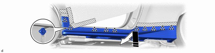
.png) | Protective Tape |
.png) | Install in this Direction |
(b) Install the 3 grommets.
(c) Install the 2 clips and 6 screws.
(d) Install the 6 clips.
(e) Remove the protective tape.
2. INSTALL REAR WHEEL HOUSE FRONT PLATE
Click here
.gif)
 Rear Wheel House Plate
ComponentsCOMPONENTS ILLUSTRATION
*1 REAR WHEEL HOUSE FRONT PLATE - - RemovalREMOVAL CAUTION / NOTICE / HINT HINT:
Use the same procedure for the RH and LH sides...

Other information:
Toyota Yaris XP210 (2020-2024) Reapir and Service Manual: Lubrication System
On-vehicle InspectionON-VEHICLE INSPECTION PROCEDURE 1. CHECK ENGINE OIL LEVEL (a) Warm up and stop the engine, then wait for 5 minutes. (b) Check that the engine oil level is between the low level and full level marks on the engine oil level dipstick...
Toyota Yaris XP210 (2020-2024) Reapir and Service Manual: Terminals Of Ecu
TERMINALS OF ECU CHECK STEREO COMPONENT EQUALIZER ASSEMBLY Terminal No. (Symbol) Terminal Description Condition Specified Condition O131-15(+B) - O131-30(GND) Power source Always 11 to 14 V O131-29(IGP) - O131-30(GND) Power source (IG) Ignition switch ON 11 to 14 V O131-14(ACC) - O131-30(GND) Power source (ACC) Ignition switch ACC 11 to 14 V O131-30(GND) - Body ground Ground Always Below 1 Ω O132-1(MC1+) - O131-30(GND) Active noise control microphone input signal Active noise control microphone LH tapped with finger Pulse generation O132-5(MC1-) - O131-30(GND) Active noise control microphone input signal Always Below 1 Ω O132-2(MC2+) - O131-30(GND) Active noise control microphone input signal Active noise control microphone RH tapped with finger Pulse generation O132-6(MC2-) - O131-30(GND) Active noise control microphone input signal Always Below 1 Ω O131-3(NEI) - O131-30(GND) Engine pulse signal Idling with warm engine Pulse generation (See waveform 1) O131-24(FLI-) Active noise control microphone output signal - - O131-9(FLI+) Active noise control microphone output signal - - O131-23(FRI-) Active noise control microphone output signal - - O131-8(FRI+) Active noise control microphone output signal - - O131-5(RRI+) Active noise control microphone output signal - - O131-20(RRI-) Active noise control microphone output signal - - O131-6(RLI+) Active noise control microphone output signal - - O131-21(RLI-) Active noise control microphone output signal - - O131-7(ASG1) Shield ground - - O131-22(ASG2) Shield ground - - O131-12(FR+) - O131-30(GND) Sound signal Active noise control system operating Pulse generation O131-27(FR-) - O131-30(GND) Sound signal Active noise control system operating Pulse generation O131-13(FL+) - O131-30(GND) Sound signal Active noise control system operating Pulse generation O131-28(FL-) - O131-30(GND) Sound signal Active noise control system operating Pulse generation O131-10(RR+) - O131-30(GND) Sound signal Active noise control system operating Pulse generation O131+25(RR-) - O131-30(GND) Sound signal Active noise control system operating Pulse generation O131-11(RL+) - O131-30(GND) Sound signal Active noise control system operating Pulse generation O131-28(RL-) - O131-30(GND) Sound signal Active noise control system operating Pulse generation O131-1(CANH) CAN communication signal - - O131-16(CANL) CAN communication signal - - (a) Waveform 1 HINT: The oscilloscope waveform shown in the illustration is an example for reference only...
Categories
- Manuals Home
- Toyota Yaris Owners Manual
- Toyota Yaris Service Manual
- Low Engine Coolant Temperature Indicator Light (Blue)
- How to connect USB port/Auxiliary jack
- How to use USB mode
- New on site
- Most important about car
Fuel Gauge
The fuel gauge shows approximately how much fuel is remaining in the tank when the ignition is switched ON. We recommend keeping the tank over 1/4 full.
