Toyota Yaris: Inner Rear View Mirror / Removal
REMOVAL
PROCEDURE
1. REMOVE INNER REAR VIEW MIRROR STAY HOLDER COVER (w/o Pre-collision System)
(a) Slide the inner rear view mirror stay holder cover to disengage the guides as shown in the illustration.
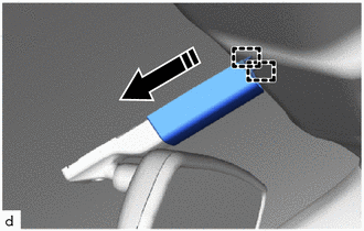
 | Slide in this Direction |
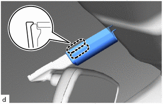
| (b) Disengage the claws to remove the inner rear view mirror stay holder cover. |
|
2. REMOVE NO. 2 FORWARD RECOGNITION COVER (w/ Pre-collision System)
Click here

3. REMOVE NO. 1 FORWARD RECOGNITION COVER (w/ Pre-collision System)
Click here

4. REMOVE INNER REAR VIEW MIRROR ASSEMBLY (w/o Pre-collision System)
(a) Disconnect the connector.
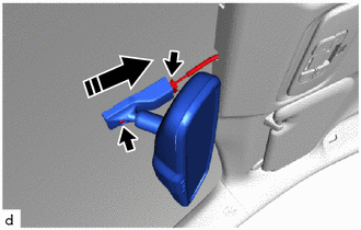
 | Remove in this Direction |
(b) Using a T20 "TORX" socket wrench, remove the screw.
(c) Remove the inner rear view mirror assembly as shown in the illustration.
5. REMOVE INNER REAR VIEW MIRROR ASSEMBLY (w/ Pre-collision System)
(a) Disconnect the connector.
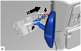
 | Remove in this Direction |
(b) Disengage the clamp.
(c) Using a T20 "TORX" socket wrench, remove the screw.
(d) Remove the inner rear view mirror assembly as shown in the illustration.
 Inspection
INSPECTION PROCEDURE 1. INSPECT INNER REAR VIEW MIRROR ASSEMBLY (a) Inspect the operation of the electrochromic inner rear view mirror assembly.
*a Black Colored Tape *b Forward Sensor *c Bright *d Dark *e Auxiliary Battery *f AUTO Switch *g Component without harness connected (Inner Rear View Mirror Assembly) - - (1) Connect a positive (+) lead from the auxiliary battery to terminal 4 (IG) and a negative (-) lead to terminal 1 (E)...
 Installation
INSTALLATION PROCEDURE 1. INSTALL INNER REAR VIEW MIRROR ASSEMBLY (w/o Pre-collision System) (a) Install the inner rear view mirror assembly as shown in the illustration...
Other information:
Toyota Yaris XP210 (2020-2024) Reapir and Service Manual: Removal
REMOVAL CAUTION / NOTICE / HINT HINT: When the cable is disconnected/reconnected to the auxiliary battery terminal, systems temporarily stop operating. However, each system has a function that completes learning the first time the system is used. Learning completes when vehicle is driven Effect/Inoperative Function When Necessary Procedures are not Performed Necessary Procedures Link Lane tracing assist system Drive the vehicle straight ahead at 35 km/h (22 mph) or more for 5 second or more...
Toyota Yaris XP210 (2020-2024) Reapir and Service Manual: A/F (O2) Sensor Signal Biased/Stuck Rich Bank 1 Sensor 2 Circuit Current Below Threshold (P227118)
DESCRIPTION Refer to DTC P003612. Click here DTC No. Detection Item DTC Detection Condition Trouble Area MIL Note P227118 A/F (O2) Sensor Signal Biased/Stuck Rich Bank 1 Sensor 2 Circuit Current Below Threshold While the fuel-cut operation is performed (during vehicle deceleration), the air fuel ratio sensor (sensor 2) current is less than 7...
Categories
- Manuals Home
- Toyota Yaris Owners Manual
- Toyota Yaris Service Manual
- Brake System Control Module "A" System Voltage System Voltage Low (C137BA2)
- Removal
- Key Battery Replacement
- New on site
- Most important about car
Keys

To use the auxiliary key, press the knob and pull out the auxiliary key from the smart key.
