Toyota Yaris: Exhaust Pipe / Removal
REMOVAL
CAUTION / NOTICE / HINT
The necessary procedures (adjustment, calibration, initialization or registration) that must be performed after parts are removed and installed, or replaced during front exhaust pipe assembly and tail exhaust pipe assembly removal/installation are shown below.
Necessary Procedures After Parts Removed/Installed/Replaced| Replaced Part or Performed Procedure | Necessary Procedure | Effect/Inoperative Function when Necessary Procedure not Performed | Link |
|---|---|---|---|
| Gas leak from exhaust system is repaired | Inspection After Repair |
|
|

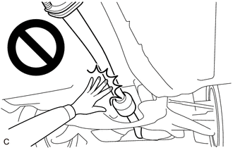
CAUTION:
To prevent burns, do not touch the engine, exhaust pipe or other high temperature components while the engine is hot.
PROCEDURE
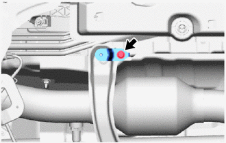
1. REMOVE TAIL EXHAUST PIPE ASSEMBLY
CAUTION:
To prevent burns, do not touch the engine, exhaust pipe or other high temperature components while the engine is hot.
| (a) Remove the 2 bolts and disconnect the tail exhaust pipe assembly from the front exhaust pipe assembly. |
|

(b) Remove the tail exhaust pipe assembly from the 3 exhaust pipe supports.
(c) Remove the exhaust pipe gasket from the front exhaust pipe assembly.
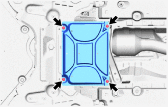
2. REMOVE CENTER NO. 4 ENGINE UNDER COVER
| (a) Remove the 4 bolts and center No. 4 engine under cover from the vehicle body. |
|
3. REMOVE FRONT FLOOR CENTER BRACE
| (a) Remove the bolt and front floor center brace from the center No.1 floor brace. |
|
4. REMOVE CENTER NO. 1 FLOOR BRACE
| (a) Remove the 2 nuts and center No. 1 floor brace from the body. |
|

5. REMOVE NO. 2 AIR FUEL RATIO SENSOR
Click here

6. REMOVE FRONT EXHAUST PIPE ASSEMBLY
CAUTION:
To prevent burns, do not touch the engine, exhaust pipe or other high temperature components while the engine is hot.
| (a) Remove the 2 bolts and 2 compression springs and disconnect the front exhaust pipe assembly from the exhaust manifold converter sub-assembly. |
|

(b) Remove the front exhaust pipe assembly from the 2 exhaust pipe supports.
(c) Remove the exhaust pipe gasket from the exhaust manifold converter sub-assembly.
 Components
COMPONENTS ILLUSTRATION
*1 TAIL EXHAUST PIPE ASSEMBLY - -
N*m (kgf*cm, ft.*lbf): Specified torque - - ILLUSTRATION
*1 NO...
 Installation
INSTALLATION PROCEDURE 1. INSTALL FRONT EXHAUST PIPE ASSEMBLY (a) Using a vernier caliper, measure the free length of the compression springs. Standard Length 43...
Other information:
Toyota Yaris XP210 (2020-2024) Reapir and Service Manual: Engine Difficult to Start
DESCRIPTION Problem Symptom Suspected Area Trouble Area Engine does not crank Engine cranks slowly Auxiliary battery depletion Starter malfunction Starter system Auxiliary battery depletion Starter malfunction Starter circuit Excessive engine friction Engine Engine assembly Starting time is long Engine speed fluctuation due to abnormal combustion Idle speed too low or high The engine stalls immediately after starting Strong engine vibration due to above symptoms Ignition malfunction Deviation in air fuel ratio (Excessive or insufficient intake air volume or fuel supply) Insufficient compression Changes in load from another system Ignition system Spark plug Ignition coil assembly Fuel system Direct fuel injector assembly Port fuel injector assembly Fuel pump assembly (for high pressure side) Fuel pump (for low pressure side) Fuel pump control circuit Fuel suction plate sub-assembly Fuel main valve assembly Fuel line Purge VSV system Fuel quality (existence of foreign matter, degradation) Intake and exhaust systems Mass air flow meter sub-assembly Intake system (Air leaks or deposit accumulation) Throttle body with motor assembly Air fuel ratio sensor (sensor 1) Air fuel ratio sensor (sensor 2) Cam timing oil control solenoid assembly Variable Valve Timing system (VVT system) Other control systems ECM Wire harness or connector Knock control sensor Engine coolant temperature sensor Immobiliser system Engine Water control valve Engine assembly Crankshaft position sensor High load from another system Air conditioning system Power steering system Electrical load signal system SYMPTOM AND CAUSE OF SYSTEM MALFUNCTION HINT: The following are descriptions of the characteristics of each system malfunction...
Toyota Yaris XP210 (2020-2024) Reapir and Service Manual: Check For Intermittent Problems
CHECK FOR INTERMITTENT PROBLEMS CHECK FOR INTERMITTENT PROBLEMS HINT: A momentary interruption (open circuit) in the connectors and/or wire harness between the sensors and ECUs can be detected using the Data List function of the GTS. (a) Follow the directions on the GTS to display the Data List and select areas where momentary interruption should be monitored...
Categories
- Manuals Home
- Toyota Yaris Owners Manual
- Toyota Yaris Service Manual
- Low Engine Coolant Temperature Indicator Light (Blue)
- To Set Speed
- Key Battery Replacement
- New on site
- Most important about car
Keys

To use the auxiliary key, press the knob and pull out the auxiliary key from the smart key.
