Toyota Yaris: Air Fuel Ratio Sensor (for Sensor 1) / Removal
REMOVAL
CAUTION / NOTICE / HINT
The necessary procedures (adjustment, calibration, initialization, or registration) that must be performed after parts are removed, installed, or replaced during the air fuel ratio sensor removal/installation are shown below.
Necessary Procedure After Parts Removed/Installed/Replaced| Replacement Part or Procedure | Necessary Procedure | Effect/Inoperative when not Performed | Link |
|---|---|---|---|
| Inspection after repair |
|
|

CAUTION:
-
When the engine is hot, do not touch high-temperature areas such as the engine or exhaust manifold.
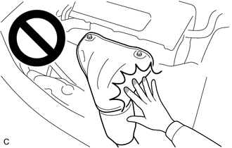
- Touching high-temperature areas such as the engine and exhaust manifold could result in burns.
PROCEDURE
1. REMOVE WINDSHIELD WIPER MOTOR AND LINK
Click here

2. REMOVE FRONT NO. 1 VENTILATOR SEAL
Click here

3. REMOVE WATER GUARD PLATE RH
Click here

4. REMOVE OUTER COWL TOP PANEL SUB-ASSEMBLY
Click here

5. SEPARATE NO. 1 AIR CLEANER HOSE
Click here

6. REMOVE INTAKE AIR RESONATOR
Click here

7. REMOVE AIR FUEL RATIO SENSOR
| (a) Disconnect the air fuel ratio sensor connector. |
|
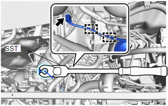
(b) Disengage the 2 clamps.
(c) Using SST, remove the air fuel ratio sensor from the exhaust manifold.
SST: 09224-00012
NOTICE:
If the air fuel ratio sensor has been struck or dropped, replace it.
 Components
COMPONENTS ILLUSTRATION
*1 WATER GUARD PLATE LH *2 NO. 1 FRONT VENTILATOR SEAL *3 OUTER COWL TOP PANEL SUB-ASSEMBLY - -
N*m (kgf*cm, ft...
 Inspection
INSPECTION PROCEDURE 1. INSPECT AIR FUEL RATIO SENSOR (a) Measure the resistance according to the value(s) in the table below. Standard Resistance: Tester Connection Condition Specified Condition D102-1(HA1A) - D102-2(+B) 20°C (68°F) 1...
Other information:
Toyota Yaris XP210 (2020-2024) Reapir and Service Manual: Installation
INSTALLATION PROCEDURE 1. INSTALL FUEL SUCTION WITH PUMP AND GAUGE TUBE ASSEMBLY (a) Install a new gasket to the fuel tank assembly. (b) Connect the fuel return vent tube sub-assembly to the fuel suction tube with pump and gauge assembly. Click here *1 Fuel Return Vent Tube Sub-assembly Front of the Vehicle Make sure to correctly assemble the fuel return vent tube sub-assembly as shown in the illustration...
Toyota Yaris XP210 (2020-2024) Reapir and Service Manual: Precaution
PRECAUTION PRECAUTION FOR DISCONNECTING CABLE FROM NEGATIVE AUXILIARY BATTERY TERMINAL NOTICE: When disconnecting the cable from the negative (-) auxiliary battery terminal, some systems must be initialized after the cable is reconnected. Click here If the auxiliary battery has been discharged and charged or the cable has been disconnected and reconnected to the negative (-) auxiliary battery terminal, perform Steering Sensor Zero Point Calibration...
Categories
- Manuals Home
- Toyota Yaris Owners Manual
- Toyota Yaris Service Manual
- Engine Start Function When Key Battery is Dead
- Diagnostic Trouble Code Chart
- Headlights
- New on site
- Most important about car
Keys

To use the auxiliary key, press the knob and pull out the auxiliary key from the smart key.
