Toyota Yaris: Ea67f (manual Transmission / Transaxle) / Neutral Position Switch
Components
COMPONENTS
ILLUSTRATION
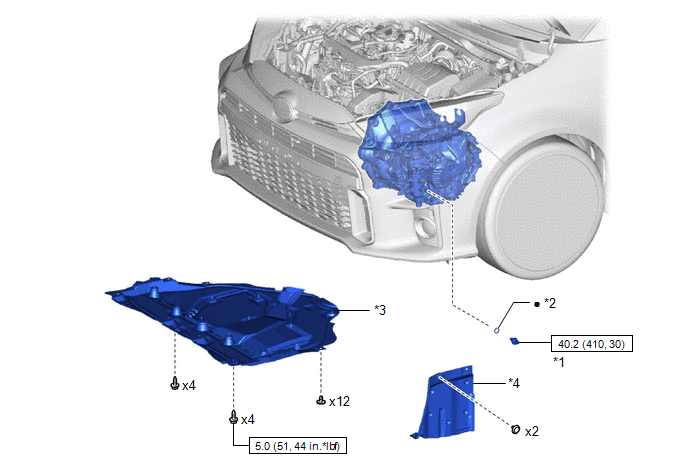
| *1 | NEUTRAL POSITION SWITCH | *2 | GASKET |
| *3 | NO. 1 ENGINE UNDER COVER ASSEMBLY | *4 | ENGINE UNDER COVER LH |
 | N*m (kgf*cm, ft.*lbf): Specified torque | ● | Non-reusable part |
Removal
REMOVAL
PROCEDURE
1. REMOVE NO. 1 ENGINE UNDER COVER ASSEMBLY
Click here

2. REMOVE ENGINE UNDER COVER LH
Click here

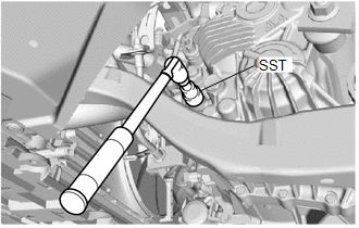
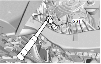
3. REMOVE NEUTRAL POSITION SWITCH
| (a) Disconnect the neutral position switch connector. |
|
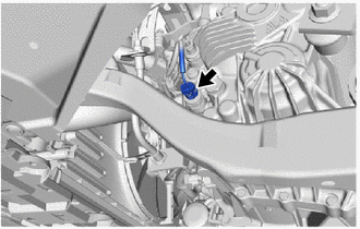
| (b) Using SST, remove the neutral position switch and gasket from the manual transaxle assembly. SST: 09816-30010 |
|
Installation
INSTALLATION
PROCEDURE
1. INSTALL NEUTRAL POSITION SWITCH
| (a) Using SST, install a new gasket and the neutral position switch to the manual transaxle assembly. SST: 09816-30010 Torque: 40.2 N·m {410 kgf·cm, 30 ft·lbf} |
|
(b) Connect the neutral position switch connector.
2. INSTALL ENGINE UNDER COVER LH
Click here

3. INSTALL NO. 1 ENGINE UNDER COVER ASSEMBLY
Click here

 Inspection
INSPECTION PROCEDURE 1. INSPECT REVERSE IDLER GEAR THRUST CLEARANCE (a) Using a feeler gauge, measure the reverse idler gear thrust clearance. Standard Clearance: 0...
 Output Shaft
..
Other information:
Toyota Yaris XP210 (2020-2024) Reapir and Service Manual: On-vehicle Inspection
ON-VEHICLE INSPECTION PROCEDURE 1. INSPECT BRAKE FLUID LEVEL IN RESERVOIR (a) Check the fluid level. HINT: If the brake fluid level is lower than the MIN line, inspect for brake fluid leaks and brake pad wear. If necessary, refill the reservoir with brake fluid to the MAX line after repair or replacement...
Toyota Yaris XP210 (2020-2024) Reapir and Service Manual: Installation
INSTALLATION CAUTION / NOTICE / HINT NOTICE: This procedure includes the installation of small-head bolts. Refer to Small-Head Bolts of Basic Repair Hint to identify the small-head bolts. Click here PROCEDURE 1. INSTALL CYLINDER HEAD GASKET (a) Clean the cylinder block sub-assembly and cylinder head sub-assembly with solvent...
Categories
- Manuals Home
- Toyota Yaris Owners Manual
- Toyota Yaris Service Manual
- How to connect USB port/Auxiliary jack
- Battery Monitor Module General Electrical Failure (P058A01)
- Fuse Panel Description
- New on site
- Most important about car
Supplemental Restraint System (SRS) Precautions
The front and side supplemental restraint systems (SRS) include different types of air bags. Please verify the different types of air bags which are equipped on your vehicle by locating the “SRS AIRBAG” location indicators. These indicators are visible in the area where the air bags are installed.
The air bags are installed in the following locations:
The steering wheel hub (driver air bag) The front passenger dashboard (front passenger air bag) The outboard sides of the front seatbacks (side air bags) The front and rear window pillars, and the roof edge along both sides (curtain air bags)