Toyota Yaris: Clutch Master Cylinder / Installation
INSTALLATION
PROCEDURE
1. INSTALL CLUTCH MASTER CYLINDER ASSEMBLY
(a) Install a new clutch master cylinder gasket to the clutch master cylinder assembly.
(b) Install the clutch master cylinder assembly to the vehicle body with the 2 nuts.
Torque:
12.7 N·m {130 kgf·cm, 9 ft·lbf}
2. INSTALL CLUTCH MASTER CYLINDER PUSH ROD CLEVIS WITH HOLE PIN
Click here

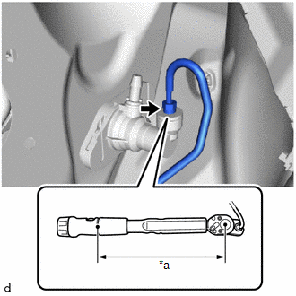
3. CONNECT CLUTCH MASTER CYLINDER TO FLEXIBLE HOSE TUBE
| (a) Using a 10 mm union nut wrench, connect the clutch master cylinder to flexible hose tube to the clutch master cylinder assembly. Torque: Specified Tightening Torque : 15.2 N·m {155 kgf·cm, 11 ft·lbf} NOTICE:
HINT:
|
|

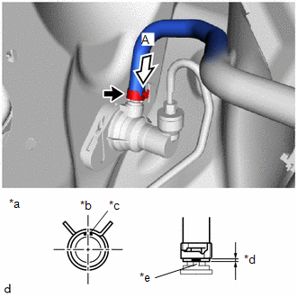
4. CONNECT NO. 1 CLUTCH RESERVOIR HOSE
| (a) Connect the No. 1 clutch reservoir hose to the clutch master cylinder assembly and slide the hose clip to secure it. NOTICE:
|
|
5. INSTALL BRAKE BOOSTER ASSEMBLY
Click here

6. BLEED CLUTCH LINE
Click here

7. INSPECT FOR BRAKE FLUID LEAK
8. INSPECT BRAKE FLUID LEVEL IN RESERVOIR
Click here

9. INSPECT CLUTCH PEDAL
Click here

 Removal
REMOVAL CAUTION / NOTICE / HINT HINT: When the cable is disconnected / reconnected to the auxiliary battery terminal, systems temporarily stop operating...
 Clutch Pedal
..
Other information:
Toyota Yaris XP210 (2020-2024) Reapir and Service Manual: Data List / Active Test
DATA LIST / ACTIVE TEST DATA LIST NOTICE: In the table below, the values listed under "Normal Condition" are reference values. Do not depend solely on these reference values when deciding whether a part is faulty or not. HINT: Using the GTS to read the Data List allows the values or states of switches, sensors, actuators and other items to be read without removing any parts...
Toyota Yaris XP210 (2020-2024) Reapir and Service Manual: Brake Switch "A"/"B" Signal Cross Coupled (P05042B)
DESCRIPTION The stop light switch assembly is a duplex system that transmits two signals: STP and ST1-. These two signals are used by the ECM to monitor whether or not the brake system is working properly. If the signals, which indicate the brake pedal is being depressed and released, are detected simultaneously, the ECM interprets this as a malfunction in the stop light switch assembly and stores this DTC...
Categories
- Manuals Home
- Toyota Yaris Owners Manual
- Toyota Yaris Service Manual
- Fuse Panel Description
- Auto Lock/Unlock Function
- Starting the Engine
- New on site
- Most important about car
Fuel Gauge
The fuel gauge shows approximately how much fuel is remaining in the tank when the ignition is switched ON. We recommend keeping the tank over 1/4 full.
