Toyota Yaris: Fuel Injector (for Direct Injection) / Components
COMPONENTS
ILLUSTRATION
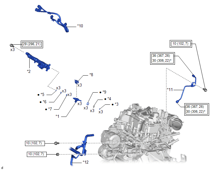
| *1 | FUEL INJECTOR ASSEMBLY | *2 | FUEL DELIVERY PIPE |
| *3 | FUEL INJECTOR SEAL | *4 | C-RING |
| *5 | NO. 3 FUEL INJECTOR BACK-UP RING | *6 | O-RING |
| *7 | NO. 1 FUEL INJECTOR BACK-UP RING | *8 | NOZZLE HOLDER CLAMP |
| *9 | INJECTOR VIBRATION INSULATOR | *10 | NO. 6 ENGINE WIRE |
| *11 | NO. 1 FUEL PIPE SUB-ASSEMBLY | *12 | NO. 2 WATER BY-PASS PIPE |
 | Tightening torque for "Major areas involving basic vehicle performance such as moving/turning/stopping": N*m (kgf*cm, ft.*lbf) |
 | N*m (kgf*cm, ft.*lbf): Specified torque |
| * | For use with SST | ● | Non-reusable part |

 Removal
REMOVAL CAUTION / NOTICE / HINT The necessary procedures (adjustment, calibration, initialization or registration) that must be performed after parts are removed and installed, or replaced during fuel injector assembly removal/installation are shown below...
Other information:
Toyota Yaris XP210 (2020-2024) Reapir and Service Manual: Reassembly
REASSEMBLY PROCEDURE 1. INSTALL STARTER CENTER BEARING CLUTCH SUB-ASSEMBLY (a) Apply high-temperature grease to the pinion drive lever as shown in the illustration. *1 Starter Center Bearing Clutch Sub-assembly *2 Starter Drive Housing Assembly *3 Pinion Drive Lever *4 Rubber Seal High-temperature Grease (b) Install the pinion drive lever and rubber seal to the starter center bearing clutch sub-assembly...
Toyota Yaris XP210 (2020-2024) Reapir and Service Manual: Vehicle Control History
VEHICLE CONTROL HISTORY CHECK VEHICLE CONTROL HISTORY HINT: The vehicle control history data stores the history of the reject function and system protection operations. The number of occurrences, date and distance are stored in batches for each item...
Categories
- Manuals Home
- Toyota Yaris Owners Manual
- Toyota Yaris Service Manual
- How to use USB mode
- Brake System Control Module "A" System Voltage System Voltage Low (C137BA2)
- Removal
- New on site
- Most important about car
Fuel Gauge
The fuel gauge shows approximately how much fuel is remaining in the tank when the ignition is switched ON. We recommend keeping the tank over 1/4 full.

Copyright © 2024 www.toyaris4.com