Toyota Yaris: Heating / Air Conditioning / Ambient Temperature Sensor
Components
COMPONENTS
ILLUSTRATION
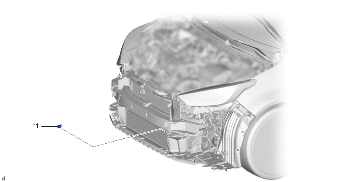
| *1 | THERMISTOR ASSEMBLY | - | - |
Removal
REMOVAL
PROCEDURE
1. REMOVE FRONT BUMPER ASSEMBLY
Click here

2. REMOVE THERMISTOR ASSEMBLY
| (a) Disengage the clamp. |
|

(b) Disconnect the connector to remove the thermistor assembly.
Inspection
INSPECTION
PROCEDURE
1. INSPECT THERMISTOR ASSEMBLY
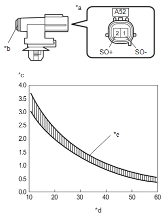
(a) Check the resistance.
| (1) Measure the resistance according to the value(s) in the table below. Standard resistance:
NOTICE:
HINT: As the temperature increases, the resistance decreases (see the graph). If the specified condition is not met, replace the thermistor assembly. |
|
Installation
INSTALLATION
PROCEDURE
1. INSTALL THERMISTOR ASSEMBLY
| (a) Connect the connector. |
|
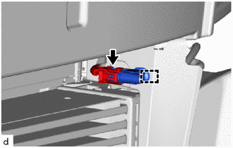
(b) Engage the clamp to install the thermistor assembly.
2. INSTALL FRONT BUMPER ASSEMBLY
Click here

 Installation
INSTALLATION PROCEDURE 1. TEMPORARILY INSTALL AIR CONDITIONER UNIT ASSEMBLY (a) Temporarily install the air conditioner unit assembly to the instrument panel reinforcement assembly with the 3 bolts...
 Blower Unit
..
Other information:
Toyota Yaris XP210 (2020-2024) Reapir and Service Manual: Terminals Of Ecu
TERMINALS OF ECU CHECK POWER DISTRIBUTION BOX ASSEMBLY (a) Remove the power distribution box assembly. Click here (b) Reconnect the power distribution box assembly connectors. (c) Measure the voltage and resistance according to the value(s) in the table below...
Toyota Yaris XP210 (2020-2024) Reapir and Service Manual: Stop Lamp Relay Actuator Stuck Off (C13807F)
DESCRIPTION Refer to DTC C13807E. Click here DTC No. Detection Item DTC Detection Condition Trouble Area DTC Output from C13807F Stop Lamp Relay Actuator Stuck Off Either of the following is detected: When the IGR terminal voltage exceeds 10 V and the +BS terminal voltage is from 9...
Categories
- Manuals Home
- Toyota Yaris Owners Manual
- Toyota Yaris Service Manual
- Low Engine Coolant Temperature Indicator Light (Blue)
- Adjustment
- Headlights
- New on site
- Most important about car
Liftgate/Trunk Lid
WARNING
Never allow a person to ride in the luggage compartment/trunk
Allowing a person to ride in the luggage compartment/trunk is dangerous. The person in the luggage compartment/trunk could be seriously injured or killed during sudden braking or a collision.
Do not drive with the liftgate/trunk lid open